Choosing Modular EV Charging Hubs: Capacity and Expansion Planning
Choose modular charging hubs by starting with the vehicles’ energy requirements and the site’s available electrical capacity, then testing whether the proposed equipment can expand without rebuilding the connection, civil works, or control system. A design that supports today’s charger count can still fail when vehicles arrive together, charging sessions take longer than expected, or a later phase requires equipment that the original switchboard cannot accommodate.
The strongest option is the one that meets a defined service level at an acceptable lifecycle cost while preserving a credible route to the next capacity stage. That requires separate decisions about charging ports, shared power, grid supply, and the physical space needed to add each one.
Translate vehicle demand into capacity requirements
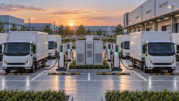
Start with an operating profile rather than a target number of chargers. Record expected vehicle types, daily energy consumption, arrival and departure windows, usable dwell time, and the minimum charge required before departure. Separate predictable depot charging from public or visitor charging, where arrivals and session lengths are less certain.
Daily energy establishes the amount of electricity the hub must deliver. Divide the required energy by the available charging window to estimate average charging power, then account for conversion losses and periods when charging is unavailable. This average is a starting point: it does not capture short periods when many vehicles need power at once.
Peak demand and daily energy answer different questions. A site with a large overnight window can deliver substantial energy with moderate power. A site serving vehicles with short turnaround times can need much higher peak power even if its daily energy total is similar. Model both conditions before selecting a connection or charger configuration.
Build at least three operating scenarios: an initial workload, a credible expansion workload, and a constrained case in which arrivals bunch together or some equipment is unavailable. For each, assess energy delivered before departure, queue length or missed service windows, and maximum site import. Include other building loads when they share the grid connection.
Distinguish port count from power capacity
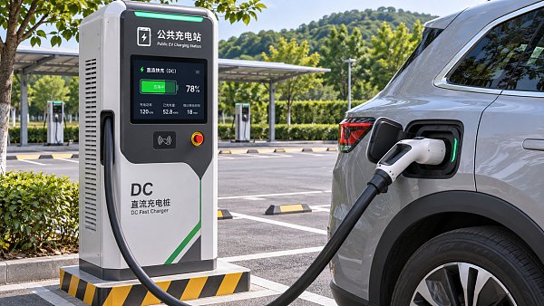
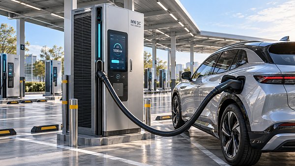
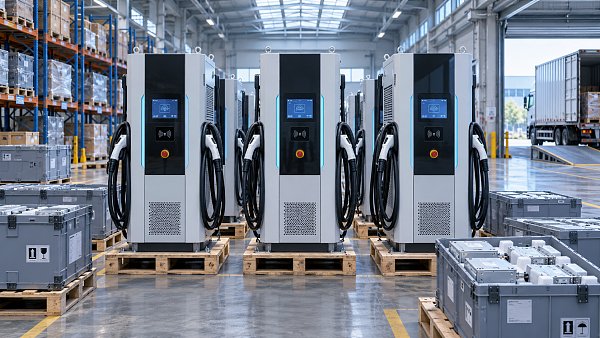
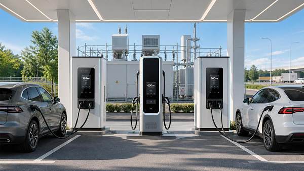
A port is a vehicle connection point; its advertised power does not necessarily represent power available at every port simultaneously. A shared DC power cabinet distributes a finite output among dispensers. If several vehicles charge together, each can receive less than the dispenser’s maximum rating. Request the power-sharing rules, allocation increments, and any limits on simultaneous sessions.
Vehicle acceptance also changes during a session. Battery temperature, state of charge, and onboard charging limits can reduce the power a vehicle draws. Use representative charging curves where available; assuming every vehicle draws nameplate power for its entire visit can overstate demand, while assuming immediate power tapering can hide an early-session peak.
Match the electrical connection to the expansion path
Obtain the available connection capacity and its operating conditions early. A utility offer, existing transformer rating, and contracted import limit are different constraints; the smallest applicable limit can govern the first phase. Confirm whether capacity is firm throughout the operating period and whether any export or generation restrictions apply.
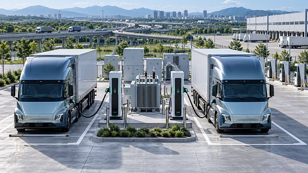
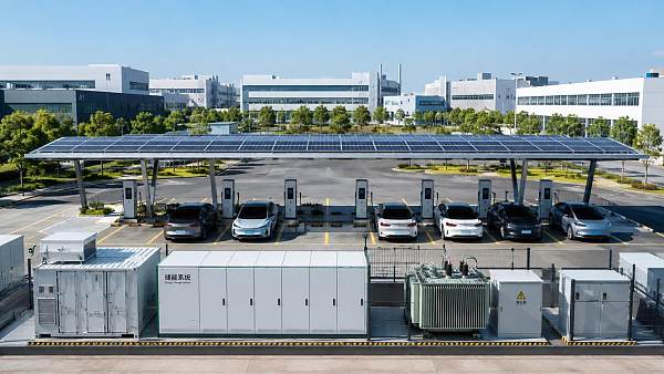
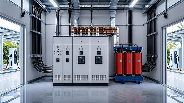
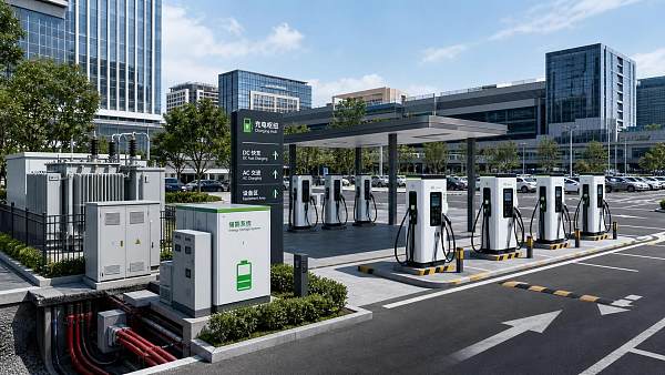
Trace power from the point of connection through protection equipment, transformer, main switchboard, distribution panels, cabling, and charger power modules. Each element needs a defined initial rating and an expansion limit. A larger transformer alone does not create usable capacity if the switchboard, upstream connection, or protection settings remain constrained.
Ask the utility about application milestones, studies, connection works, outage requirements, and the process for requesting additional capacity. Place these activities on the project schedule before committing to equipment delivery dates. Where future capacity is uncertain, document a viable operating mode under the initial limit rather than assuming an upgrade will arrive on time.
Design calculations also need to account for cable routes, voltage drop, fault levels, protective-device coordination, and local installation requirements. Leave room in switchgear and distribution equipment only where the manufacturer permits the intended additions; an empty physical space is not proof that a future feeder can be installed.
Compare modular architectures against the duty cycle
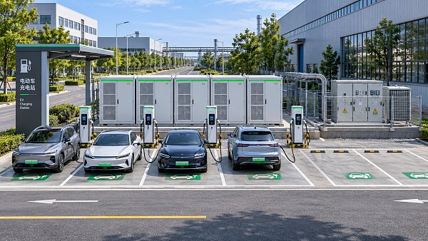
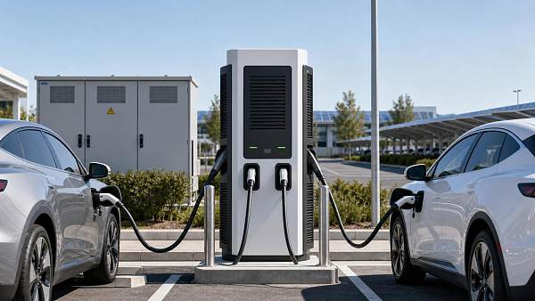
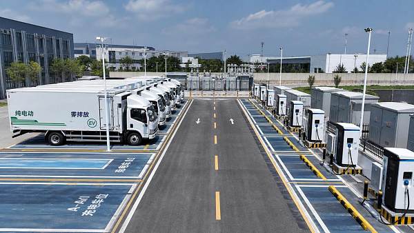
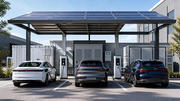
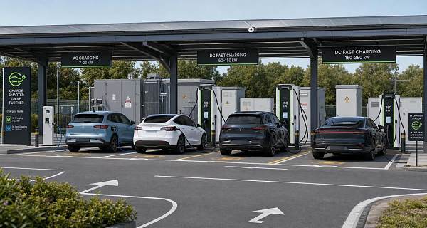
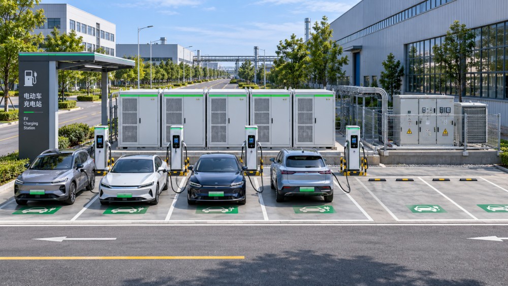
Modularity can refer to replaceable power modules, expandable cabinets, additional dispensers, or a combination of these. Two systems described as modular can have very different expansion limits. Compare their first-stage capacity with the largest supported configuration, including any additional controls, cooling, protection, or civil works required between those points.
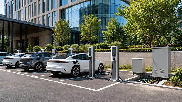
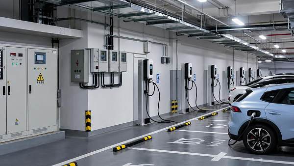
- Distributed chargers: Individual units can be installed in stages and isolate some equipment failures, but each added unit requires suitable distribution capacity and a cable route.
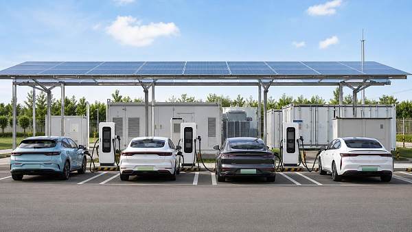
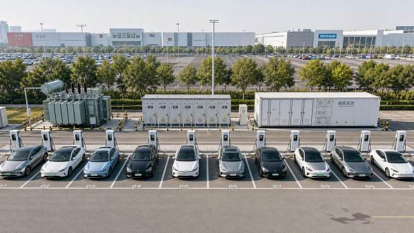
- Shared power cabinets: Multiple dispensers draw from a common pool, which can make use of staggered demand. A cabinet or communications failure can affect several bays, so the failure response needs examination.
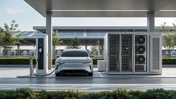
- Expandable power modules: Additional modules can increase cabinet output within its certified configuration. Confirm module availability, installation constraints, and whether existing cooling and upstream equipment support the final rating.
Compare the usable output under simultaneous charging, not just the largest number printed on a dispenser. Request allocation examples for the actual vehicle mix: one high-power vehicle arriving alone, several vehicles charging together, and a priority vehicle arriving when the cabinet is already busy. Include any limits on output voltage and current, because a suitable power rating alone does not establish compatibility with every vehicle.
For heavy or high-utilization use, cable length, connector handling, cooling arrangements, and dispenser placement affect day-to-day operation. Verify that vehicles can reach connectors without blocking adjacent bays or forcing cables across circulation routes. Equipment service access must remain available after future dispensers are installed.
Reserve site space where retrofits are disruptive
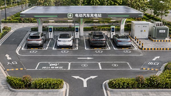
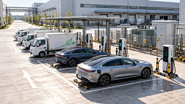
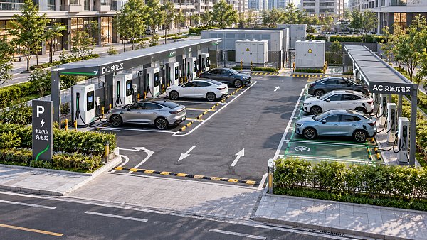
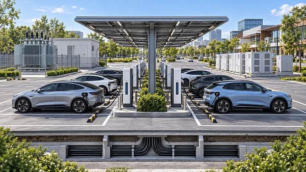
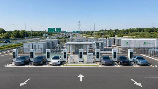
Prepare a site layout for the initial installation and each anticipated expansion stage. Show vehicle entry and exit, turning paths, accessible bays where required, equipment clearances, delivery access, and maintenance routes. A spare parking bay is not necessarily a usable charging bay if a vehicle or dispenser would obstruct circulation.
Below ground, reserve routes for power and communications cables before paving or other site work is completed. Consider spare conduits, draw pits, and crossings sized for the planned architecture, subject to the detailed electrical design. Above ground, reserve space for cabinets, switchgear, transformer works, protective barriers, and ventilation or cooling clearances.
Early civil provision has value when later excavation would interrupt operations, damage finished surfaces, or require a difficult road crossing. It also has a cost: unused conduits and oversized foundations tie up capital and can become unsuitable if the expansion design changes. Identify which routes are hard to recreate and keep those provisions tied to a documented future layout.
Set load management rules before selecting controls
A load management system can hold total charging demand within an agreed site limit by adjusting power across active sessions. Its effectiveness depends on the information available and the rules it follows. If a site shares a connection with a building, the controller needs reliable measurement of the relevant site load and enough response capability to avoid exceeding the limit.
Define priority in operational terms: departure time, minimum energy requirement, vehicle assignment, or another agreed rule. Equal power sharing is straightforward, but it can leave an urgent vehicle undercharged while another remains connected with ample time available. Test the proposed allocation against actual shift patterns and late arrivals.
Specify behavior when communications or metering fails. A controller that continues using stale measurements can breach the site limit; a conservative fallback can protect the connection but reduce charging service. Confirm where the control logic runs, how quickly limits are applied, and whether local operation continues during a network outage.
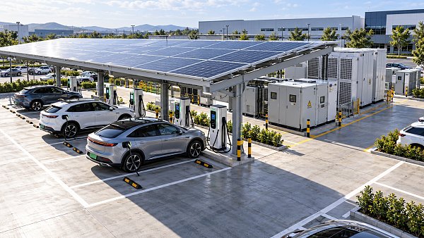
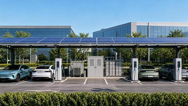
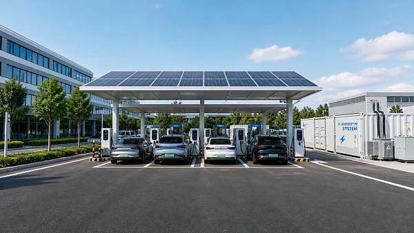
Battery storage can reduce grid peaks or supply short bursts of charging power, but it needs sufficient stored energy and time to recharge. Size it against the sequence of charging sessions and the available import capacity, not against peak charger power alone. Include conversion losses, usable battery capacity, operating restrictions, and replacement or maintenance assumptions in the comparison with a direct grid upgrade.
Protect interoperability and maintenance options
Confirm that vehicles, connectors, chargers, payment or access systems, and the management platform work together in the intended operating region. Identify which communications functions are supported in the proposed configuration, including remote monitoring, charging schedules, session data, fault reporting, and any external energy-management interface. A protocol listed on a data sheet does not guarantee that every required function is implemented or tested.
Expansion also depends on what remains compatible over time. Obtain the supported power-module and dispenser combinations, software version requirements, spare-parts arrangements, and the procedure for integrating later equipment. Ask whether adding a cabinet or changing a controller requires a site-wide outage, recommissioning, or a change to the service agreement.
Define a service response around failure impact. A failed connector at one bay and a failed shared cabinet can produce different operational consequences even when both appear as a charger outage. Remote diagnostics, local access to replacement parts, and a documented manual or fallback operating procedure help establish the practical recovery time.
Compare phased costs and commit to expansion triggers
Evaluate alternatives over the same operating horizon and demand scenarios. Include connection and utility works, electrical equipment, trenching, installation, commissioning, software, maintenance, electricity charges, and the cost of later additions. Where relevant, compare demand charges and contracted-capacity costs alongside energy consumption. State assumptions about utilization and future equipment explicitly; a low initial price can shift expenditure into a later shutdown or connection upgrade.
Set expansion triggers against service and infrastructure constraints rather than a calendar date alone. Useful signals include repeated queues during a defined operating window, vehicles leaving below their required charge, sustained use of the available site import, or lead times that require an upgrade decision before capacity is exhausted. Investigate the cause first: a queue can reflect too few ports, insufficient shared power, slow vehicle acceptance, or a poorly configured priority rule.
Record the decision as a staged capacity schedule: the connection and equipment installed now, the maximum supported by reserved infrastructure, the next approval or utility milestone, and the operating conditions that trigger each addition. Update it when vehicle schedules, tariffs, or the connection offer change, so that the next phase starts from verified constraints rather than an obsolete forecast.
Questions about market trends? Contact Market Scope Live for deeper business insights.
We respect your privacy. Your information is strictly confidential.
Related News
 EV Charging InfrastructureChoosing Modular EV Charging Hubs: Capacity and Expansion PlanningExplore how modular charging hubs can meet EV demand today and expand efficiently, with practical guidance on power capacity, site design, and lifecycle costs.MORE+
 EV Charging InfrastructureHow to Use Public EV Charging Stations: Costs, Connectors and PaymentLearn how to use public EV charging stations, compare costs, choose compatible connectors and pay with confidence on your next trip.MORE+
 EV Charging InfrastructurePlanning an EV Charging Hub: Grid Capacity, Site Layout and Power NeedsPlan charging hubs infrastructure with confidence. Explore grid capacity, site layout and power needs to build a scalable, efficient EV charging hub.MORE+
 EV Charging InfrastructureIndian Minister Proposes Lower EV Charging Rates to Encourage AdoptionIndia EV charging rates could fall in Maharashtra under Nitin Gadkari’s proposal. Explore the potential impact on drivers, fleets and charging operators.MORE+
 EV Charging InfrastructureEV Charging for Industrial Parks: Sizing Capacity and Managing Peak LoadsPlan industrial parks EV charging with confidence. Learn how to size capacity, manage peak loads, reduce demand costs, and keep fleets ready without disrupting production.MORE+
 EV Charging InfrastructureArlington County, Virginia, to Raise Public EV Charging Rates by 72%Arlington County public EV charging rates will rise 72% to $0.30/kWh on November 1, 2026. Explore the potential impact on fleet budgets and how businesses can prepare.MORE+
 EV Charging InfrastructurePlanning Solar EV Charging Hubs: Sizing PV, Battery Storage, and Grid CapacityPlan solar EV charging hubs with confidence. Learn how to size PV, battery storage, and grid capacity to meet peak demand, control costs, and support reliable charging.MORE+
 EV Charging InfrastructureChery Unveils 1.44 MW Charging System, Claims 500 km of Range in Five MinutesChery’s 1.44 MW charging system claims 500 km of range in five minutes. Explore its ultrafast EV charging technology, vehicle compatibility and global rollout plans.MORE+
 EV Charging InfrastructureComparing EV Charging Equipment Manufacturers: Warranty, Lead Times, and SupportCompare EV charging equipment manufacturers on warranty coverage, lead times, and support. Discover how to reduce downtime, uncover hidden costs, and choose the right supplier.MORE+
 EV Charging InfrastructurePlanning Urban EV Charging Hubs: Site Selection, Power Needs, and Charger MixPlan urban EV charging hubs with confidence. Discover how to select sites, size power capacity, and balance AC/DC chargers to control costs and deliver reliable charging.MORE+
 EV Charging InfrastructureHow to Plan Charging Corridors for Fleet Routes, Grid Capacity, and Future DemandCharging corridor infrastructure planning helps fleets align routes, grid capacity, reliable charging, and scalable site design for future demand.MORE+
 EV Charging InfrastructureHow to Size Fast EV Charging Equipment for Fleet Depots Without OverbuildingFast EV charging equipment for fleet depots: learn how to match power, charging windows, grid capacity, and smart controls without costly overbuilding.MORE+
 EV Charging InfrastructureHow to Plan EV Charging Infrastructure in Indonesia for Fleet and Public SitesCharging infrastructure planning in Indonesia for fleet and public sites: optimize energy, grid capacity, smart load management, safety, and scalable EV charging.MORE+
 EV Charging InfrastructureHow to Size DC EV Charging Equipment for Fleet Depots and Peak DemandDC EV charging equipment sizing guide for fleet depots: balance energy demand, peak loads, utility limits, smart charging, and scalable growth.MORE+
 EV Charging InfrastructureAre EV Charger Payment Systems Interoperable Across Regions?Are there interoperability standards for EV charger payment systems across regions? Explore OCPP, OCPI, Plug & Charge, roaming, and payment strategies for seamless EV charging.MORE+
 EV Charging InfrastructureHow to Evaluate Total Cost of Ownership for a Fleet DC Charging DepotHow to evaluate total cost of ownership for a fleet DC charging depot: compare grid costs, tariffs, uptime, smart charging, and scalable infrastructure.MORE+
 EV Charging InfrastructurePublic Charging Infrastructure Planning: Site Criteria, Grid Capacity, and UtilizationPublic charging infrastructure planning made practical: evaluate site access, grid capacity, utilization, and scalable design to build reliable, investable EV charging hubs.MORE+
 EV Charging InfrastructureHow Behind-the-Meter Energy Systems for EV Charging Cut Peak-Demand CostsBehind the meter energy systems for EV charging help cut peak-demand costs, defer grid upgrades, and improve charging reliability with storage and smart controls.MORE+
 EV Charging InfrastructureIs Building a Public EV Charging Network in Rural Areas Financially Viable?Is it financially viable to build public charging networks in rural areas? Explore grid costs, utilization, funding, AC/DC choices, and strategies for profitable rural EV charging.MORE+
 EV Charging InfrastructureHow Public EV Charging Load Management Prevents Peak Demand and Grid Overloadspublic EV charging load management prevents costly peak demand and grid overloads. Explore smarter controls, capacity planning, and scalable charging performance.MORE+
 EV Charging InfrastructureHow to Assess Long-Term EV Charger Reliability Before ProcurementHow to evaluate long-term reliability of EV chargers before procurement? Explore practical checks for uptime, grid compatibility, software stability, service support, and lifecycle costs.MORE+
 EV Charging InfrastructureIs AC Charging Still Worth Investing in for New Public Stations in 2026?Is AC charging still worth investing in for new public stations in 2026? Explore where smart, managed AC charging delivers value, revenue, and scalable EV infrastructure.MORE+
 EV Charging InfrastructureHow to Plan Power Capacity for Highway EV Charging CorridorsHighway charging corridor power capacity planning: learn how to size grid connections, manage peak demand, use storage, and phase EV hubs for reliable, scalable growth.MORE+
 EV Charging InfrastructureWhat Is the Typical BMS Failure Rate in EV Charging Equipment?Battery management system failure rate in charging equipment: learn what BMS faults mean, key risks, and how to protect EV charger uptime.MORE+
 EV Charging InfrastructureHow Should Fleet Depot Charging Stations Be Laid Out?Fleet depot charging station layout design guidelines for safer vehicle flow, smart power use, scalable infrastructure, and reliable fleet readiness. Explore practical planning tips.MORE+
 EV Charging InfrastructureDC Fast Chargers vs Liquid-Cooled Ultra-Fast Chargers in 2026DC fast charger vs liquid-cooled ultra-fast charging stations 2026: compare power, costs, grid demands, uptime, and ideal deployment scenarios for smarter EV infrastructure.MORE+
 EV Charging InfrastructureWhat Does the Global EcoPower Charging Intelligence Platform Do?Global EcoPower EV charging infrastructure intelligence platform delivers actionable insights on grid capacity, storage, technology, risk, and profitable charging project planning.MORE+
 EV Charging InfrastructureHow Global EcoPower Manages Energy Across EV Charging NetworksGlobal EcoPower energy management systems for charging networks optimize EV charging with dynamic load control, storage, solar integration, and reliable data insights.MORE+
 EV Charging InfrastructureWhat Switchgear Specifications Are Needed for a 500 kW Charging Site?What switchgear specifications are required for a 500kW charging installation? Explore load sizing, transformer selection, fault ratings, protection, and expansion planning.MORE+
 EV Charging InfrastructureWhich Communication Protocols Matter When Mixing Charger Brands?What communication protocols matter most when mixing charger brands at one station? Explore OCPP, OCPI, ISO 15118, and energy controls for reliable interoperability.MORE+
 EV Charging InfrastructureWhat Grid Connection Capacity Does a 10-Bay Fast Charging Hub Need?What grid connection capacity is needed for a 10-bay fast charging hub? Explore demand, power sharing, batteries, and scalable planning for reliable EV charging.MORE+
 EV Charging InfrastructureHow to Plan EV Charging Systems for Apartments Without Overloading the Building?EV charging systems for apartments start with capacity, not charger count. Learn how to prevent overloads, use smart load management, and plan scalable charging that fits your building.MORE+
 EV Charging InfrastructureHow City Charging Infrastructure Planning Can Reduce Costs and Avoid Grid BottlenecksCharging infrastructure planning for cities helps cut costs, avoid grid bottlenecks, and speed EV rollout with smarter, scalable deployment.MORE+
 EV Charging InfrastructureEU Mandates EN 61851-23:2026 for EV ChargersEU Mandates EN 61851-23:2026 for EV Chargers: learn how the new EU rule impacts certification, customs clearance, and market access before October 2026.MORE+
 EV Charging InfrastructureITC Ruling Puts Chinese EV Chargers Under 337 PressureITC ruling on Chinese EV chargers puts Section 337 pressure on imports, compliance, and OEM supply chains. Learn how patent risks may impact U.S. customs, distributors, and EV charger sourcing.MORE+
 EV Charging InfrastructureHow EV Charging Technology Affects Charging Speed, Compatibility, and Site PlanningEV charging technology shapes real charging speed, vehicle compatibility, and site planning. Learn how to avoid costly design mistakes and build charging projects that perform.MORE+
 EV Charging InfrastructureUS Requires UL 1741 SA-2025 EVSE ModulesUS Requires UL 1741 SA-2025 EVSE Modules for imported DC fast chargers. Learn how V2G, FCC+UL testing, and firmware compliance will reshape US market access.MORE+
 EV Charging InfrastructureUSTR Opens Section 301 Review on China EV ChargersUSTR Opens Section 301 Review on China EV Chargers: learn how the 25% tariff review may affect import costs, customs compliance, and procurement timing across EV charging and BESS supply chains.MORE+
 EV Charging InfrastructureHow to Plan Fleet Charging Infrastructure for Logistics Depots and Delivery HubsFleet charging infrastructure for logistics starts with duty cycles, dwell time, and grid limits. Learn how to design depot and hub charging that cuts bottlenecks and supports scalable fleet electrification.MORE+
 EV Charging InfrastructureWhat Is Load Management in EV Charging and How Does It Reduce Peak Power Costs?Load management in EV charging helps control peak demand, lower grid upgrade pressure, and cut costly power spikes. Learn how smart power allocation improves site economics.MORE+