
Electric vehicle charging networks are becoming active power systems rather than passive collections of charge points. A site may serve a few overnight AC sessions, a cluster of high-power DC chargers, or an entire fleet depot with tightly scheduled vehicle departures. In each case, energy demand changes with vehicle arrival patterns, battery state of charge, ambient temperature, charger availability, and the local grid condition. Global EcoPower energy management systems for charging networks frame this operational challenge around coordinated power control, accurate measurement, and infrastructure planning that can adapt as charging demand grows.
A charging session begins with a request for energy, but the network must decide how that request fits within the site's present electrical limits. The charger, switchgear, transformer, utility connection, on-site generation, battery storage, and supervisory software all influence the answer. If these elements are planned separately, a charging hub can have unused equipment capacity in one part of the system while another part becomes a bottleneck. Coordinated energy management connects those layers and turns a fixed grid connection into a more flexible operating resource.
Power limits need to be visible before they become constraints
The nameplate rating of a charger does not describe the power it will always draw. A DC charger may have several connectors sharing a common power cabinet. Its output can be limited by internal module availability, cable temperature, vehicle acceptance rate, site demand limits, or a temporary dispatch instruction. Likewise, a vehicle connected to a high-power charger may initially accept substantial power and then taper as its battery approaches a higher state of charge. Energy management needs to work with live values rather than assume that every connector draws its maximum rating at the same time.
The first operational boundary is usually the point of common coupling: the location where the charging site connects to the distribution network. Metering at this point should capture import power, export power where applicable, voltage, current, power factor, frequency, and interval demand. Downstream metering adds useful detail at transformer secondary panels, charger groups, storage inverters, photovoltaic inverters, and major building loads. A single meter at the utility connection can show that a limit was exceeded, but it cannot explain whether the cause was simultaneous vehicle charging, an HVAC load, a battery control issue, or a measurement fault.
Electrical limits should also be separated by time scale. A transformer thermal loading limit may allow a short-duration peak under defined operating conditions but not sustained overload. A utility tariff may measure demand over a billing interval. A distribution feeder can have a local capacity restriction that differs from the contracted site limit. Treating these as one number leads to blunt control behavior. A practical control model identifies hard protection limits, contractual demand thresholds, equipment operating margins, and optional cost targets as distinct constraints.
Dynamic load management allocates available capacity
Dynamic load management continuously calculates the power available for charging after accounting for other site loads and operating reserves. It then allocates that power across connected vehicles. The calculation can be simple at a small site, but it becomes more involved where chargers share cabinets, multiple electrical panels feed the network, or energy storage and local generation are present.
Allocation rules need an explicit operational purpose. At a public destination site, preserving a reasonable charging experience across occupied connectors may matter more than maximizing power to the first vehicle connected. At a depot, the departure schedule and required energy for each vehicle commonly take priority. Along a corridor, keeping a portion of capacity available for newly arriving vehicles can reduce the impact of an extended session occupying a connector. These priorities should be configured as auditable rules, with a clear fallback mode when upstream communications are unavailable.
- Equal sharing can distribute available power across active sessions and is easy to explain, although it may delay vehicles with near-term departure requirements.
- Priority-based allocation assigns higher power to selected sessions based on reservation status, service class, state of charge, or a defined departure window. The priority source should be validated because inaccurate schedule data can distort the entire queue.
- Minimum-service allocation reserves a modest charging level for each connected vehicle, then assigns remaining capacity to higher-priority demand. This can be useful where long dwell times are expected.
- Demand-cap control reduces charging output when measured site load approaches a predetermined threshold. It requires sufficient response speed and should account for meter refresh delays, control latency, and the ramp behavior of the chargers.
Control granularity matters. A command to limit an entire site may avoid an overload but unnecessarily interrupt available charging capacity. Group-level control can isolate a congested feeder, while connector-level control supports finer allocation. The hardware must be able to accept and enact those commands reliably. Charger firmware, charging protocols, backend interfaces, and local controllers should be reviewed together; a theoretical control strategy cannot compensate for unsupported commands or delayed telemetry.
Storage changes the shape of the charging load
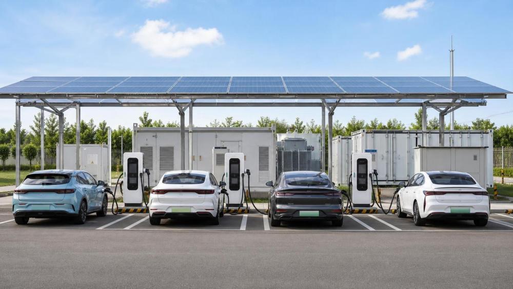
Battery energy storage can support a charging network when grid capacity is constrained, when demand spikes are short, or when local renewable generation creates variable output. The storage system does not remove the need for grid connection planning. Instead, it can shift energy in time and supply additional power during selected intervals, subject to its usable capacity, inverter rating, state-of-charge limits, cell temperature, and battery management constraints.
Two ratings are often confused during early planning: energy capacity and power capability. Energy capacity indicates how much electricity the system can store, while power capability sets how quickly it can charge or discharge. A battery with ample stored energy may still be unable to support several fast chargers if its power conversion system is undersized. Conversely, a high-power system with limited energy capacity may manage brief peaks but not cover an extended period of heavy charging. Control settings must protect a state-of-charge reserve so that the battery is not depleted before the period it was intended to support.
Storage dispatch also needs coordination with charger demand. A simple approach is to discharge whenever site import rises above a threshold and recharge whenever it falls below another threshold. That can work in stable conditions, but it may cause repeated cycling if the load moves around the threshold. More refined logic considers anticipated vehicle arrivals, charging reservations, daily operating windows, expected solar output, and the recharge power available without creating a new demand peak. Forecasts should remain advisory rather than absolute because actual charging behavior can diverge from bookings or historical patterns.
Physical integration deserves the same attention as control integration. Containerized systems require space for access, ventilation arrangements, cable routing, fire safety provisions, and maintenance clearances. Equipment placement affects trench routes, voltage drop, installation sequencing, and emergency access. Battery cells, cooling equipment, power conversion units, transformers, and protection devices need compatible specifications. A delay in one long-lead component can hold up commissioning of the whole charging hub, particularly when factory testing, transport restrictions, and site civil works are not aligned.
Charging demand and renewable generation rarely follow the same clock
On-site solar generation can lower grid imports when production coincides with charging demand, but a photovoltaic array should not be treated as a guaranteed charging supply. Cloud cover, seasonal irradiance, module soiling, inverter clipping, curtailment settings, and building shading all affect output. At some sites, the largest charging demand may occur after solar production declines. Storage, flexible charging windows, and grid import remain necessary parts of the operating design.
The control hierarchy must define what happens when local generation exceeds instantaneous site demand. Depending on interconnection conditions, surplus energy may charge storage, reduce inverter output, supply other site loads, or be exported. Reverse power flow protection, export constraints, and meter configuration need to be assessed before an operating rule is enabled. Incorrect current transformer orientation or inconsistent meter scaling can make a controller interpret imports as exports, producing poor dispatch decisions and potential protection conflicts.
Where several distributed assets are present, a local energy controller can coordinate charging, storage, generation, and building loads without relying on a permanent external connection for every command. Cloud-based monitoring still has value for reporting, asset comparison, configuration management, and long-term analysis, but essential safety and power-limit logic should continue through a resilient local path. Loss of communications should lead to a defined degraded operating mode, such as a conservative charging cap, rather than uncontrolled return to maximum charger output.
Data quality determines whether optimization is trustworthy
Energy management depends on data from meters, chargers, vehicles, storage systems, and grid interfaces. These sources may report at different intervals and use different timestamps. A charger could send a session status quickly while a revenue meter reports on another cycle. If the controller combines stale meter data with fast-changing charging measurements, a demand cap can react too late. Time synchronization, communication health checks, and data freshness flags should be part of the system design.
A useful operational view separates instantaneous power from accumulated energy. Power explains the immediate loading condition and supports control actions. Energy indicates what was delivered over time and assists with settlement, performance review, and fault investigation. Session records should retain connector identification, start and stop timestamps, requested and delivered energy where available, power limitation events, communication interruptions, and fault codes. These records make it possible to distinguish a vehicle-side charge taper from a site-imposed limit or equipment malfunction.
Interoperability should be examined beyond a statement that a charger is networked. The project needs to identify the protocol version, command set, telemetry fields, error handling behavior, cybersecurity controls, credential management, and ownership of configuration access. Firmware updates can change charging behavior or communications compatibility. Updates should therefore be staged, documented, and tested against representative equipment before broad release. A network-wide change during a busy period can create simultaneous reconnection attempts, misleading alarms, or temporarily unavailable chargers.
Commissioning is where the energy model meets the real site
Before energization, the installed cable sizes, protection settings, transformer taps, meter locations, phase assignments, and equipment addresses should be compared with the approved electrical design. Small discrepancies can undermine later control. A meter on the wrong feeder, a reversed phase sequence, or an unreported change in charger cabinet grouping can make a well-designed dispatch model behave unpredictably.
Functional testing should use realistic operating scenarios rather than only individual equipment checks. Tests may include several chargers requesting power at once, a sudden rise in non-charging load, storage discharge at the site limit, loss of cloud connectivity, restoration of communications, photovoltaic output changes, and a failed meter signal. Observers should verify both the electrical result and the event record. A controller that limits load correctly but fails to log the reason leaves maintenance teams without the evidence needed to diagnose recurring behavior.
Setpoints should be documented with their purpose, owner, revision date, and approval path. Demand caps, charging priorities, battery reserve levels, export limits, and alarm thresholds often change after the site enters service. Without change control, a temporary setting can remain in place and quietly reduce available charging capacity or increase operating cost. The same record should identify whether a setpoint is driven by equipment protection, interconnection conditions, operational preference, or a commercial requirement.
Operations depend on maintaining both electrical and digital assets
Routine maintenance includes visible inspection of connectors, cable strain relief, cooling components, enclosures, filters, foundations, labels, and drainage around outdoor equipment. High-power systems may use liquid-cooled cables or power electronics that require condition monitoring beyond basic connector checks. Contamination, water ingress, damaged seals, blocked airflow, and loose terminals can lead to derating or faults before a complete outage occurs.
Digital maintenance is equally practical. Communication loss rates, repeated authorization failures, meter drift, unexpected power sharing behavior, storage state-of-charge deviations, and recurring thermal alarms can reveal emerging problems. Trend analysis should be paired with field verification because a flat power profile might indicate successful demand control, an idle site, an unavailable charger, or missing telemetry. Alarm rules should avoid flooding the maintenance queue with duplicate events; grouping related alarms around a root condition makes response more manageable.
Energy-managed charging works best when site design, electrical protection, charging controls, storage operation, and data governance are treated as one operating system. The resulting network can respond to actual grid conditions and vehicle demand without assuming that every charger must draw its maximum power at every moment.