How to Plan EV Charging Infrastructure in Indonesia for Fleet and Public Sites
Begin with the vehicles' daily energy requirement and available dwell time, then test whether the intended site can deliver that energy without creating an unmanageable grid connection or operating bottleneck. This sequence prevents a common failure in charging infrastructure planning in Indonesia: installing chargers sized around their nameplate output while the electrical supply, vehicle schedule, or parking layout supports only a fraction of that capability.
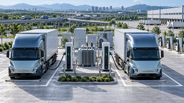
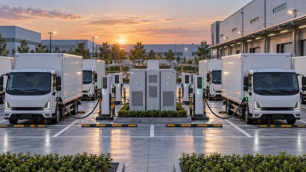
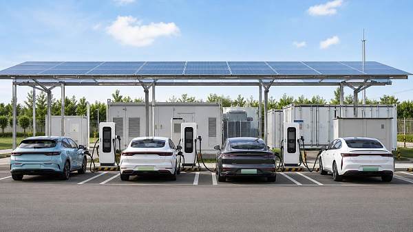
Fleet depots and public sites require different design logic. A depot can use planned overnight or between-shift charging to control peak demand. A public location must handle uncertain arrival times, varying battery states, short parking stays, payment access, and a wider range of vehicle models. Both need a design that connects vehicle behavior, electrical capacity, civil works, communications, and maintenance from the earliest site review.
Start with energy and dwell time, not charger quantity
The useful planning question is: how many kilowatt-hours must be delivered during each parking window? A fleet vehicle returning with a known state of charge, leaving at a fixed time, and parking for several hours often needs less charger power than assumed. A lower-power AC or managed DC charging arrangement may restore the required energy across the available window while avoiding a large demand spike.
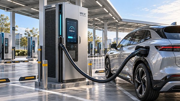
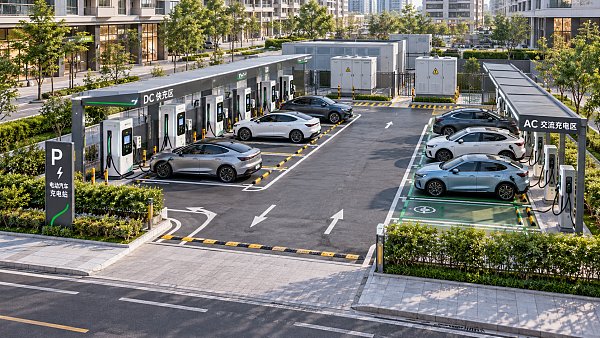
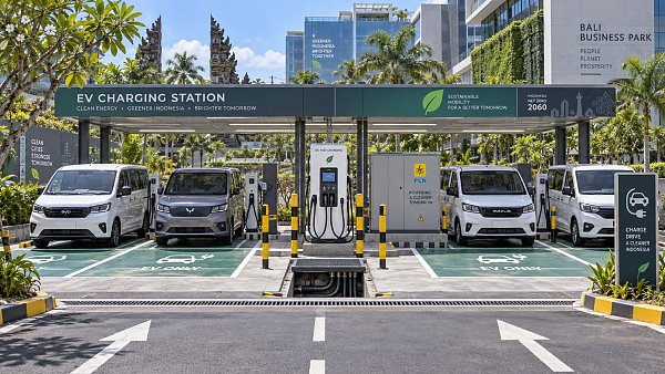
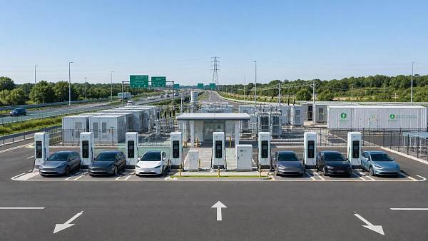
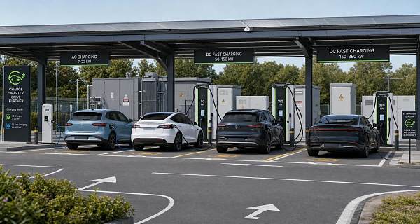
Public charging has less predictable dwell time. A destination site such as a retail area, hotel, office complex, or visitor attraction can suit AC charging where vehicles remain parked long enough. A corridor stop, urban taxi queue, or logistics transfer point has a shorter usable window and may require DC charging. Yet even a high-power charger cannot ensure fast turnaround if a vehicle limits its intake power, the battery is cold or hot, the connector is occupied, or upstream power is being shared among several dispensers.
Build a vehicle-operation profile before selecting equipment. Record arrival and departure windows, distance driven between charging events, expected energy use under actual payload and traffic conditions, parking bay turnover, and the minimum charge needed for the next trip. Separate normal operation from contingency operation. A depot designed only for an average day can fall behind after a delayed return, route diversion, or a vehicle arriving with a lower-than-planned battery level.
Confirm the electrical path before fixing the charger rating
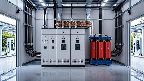
A charger is only one element in the power path. The site assessment must trace capacity from the utility point of connection through the transformer, main distribution board, feeders, protective devices, charging cabinet, and final charging outlet. Existing load matters as much as nominal service size. Air-conditioning, refrigeration, production equipment, pumps, lighting, and other loads may coincide with charging demand at the worst possible time.
Do not treat a transformer rating as spare charging capacity. Review interval load data where available and identify the actual peak, its duration, and the operational reason behind it. A site with a brief but recurring afternoon peak has a different constraint from a site carrying a stable high base load. The first may benefit from charging schedules that avoid a narrow period; the second may require a service upgrade, storage, or a lower initial charging allocation.
Grid connection discussions should begin while the layout and vehicle model are still flexible. The relevant questions include the feasible connection voltage, available import capacity, transformer location, feeder route, metering arrangement, protection requirements, and the time required for connection works. Requirements should be confirmed with the relevant local electricity authority and site owner rather than assumed from another Indonesian location. Conditions can differ between urban commercial areas, industrial estates, remote facilities, and island-based sites where network strength and construction access vary substantially.
Power quality and protection coordination deserve early engineering attention. DC charging equipment uses power electronics and may introduce harmonics or react differently to voltage disturbance than conventional site loads. Long cable runs can affect voltage drop and fault protection. Selective coordination between upstream and downstream breakers is needed so that a local charger fault does not unnecessarily interrupt the entire charging area. Earthing design, surge protection, and lightning protection require particular care in exposed outdoor locations.
Use managed load as a design tool
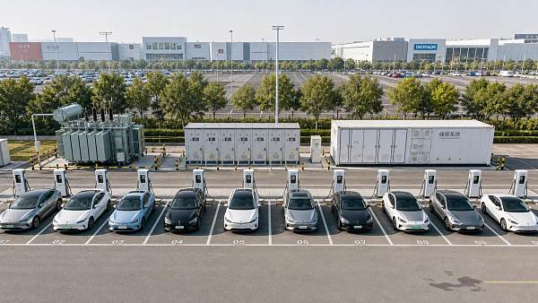
Load management changes the infrastructure decision because installed connector count does not have to equal simultaneous maximum power. At a fleet depot, a central controller can allocate available power according to departure time, required energy, vehicle priority, and site demand. The plan should state the control rule explicitly. “Smart charging” is too vague for a technical scope.
For example, a system can reserve enough power for vehicles leaving earliest, distribute remaining capacity among later departures, and reduce charging when the building approaches an agreed import threshold. This requires dependable vehicle data or an operational process for entering departure targets. Without reliable inputs, the controller may allocate power efficiently but still fail the transport schedule.
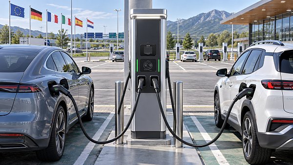
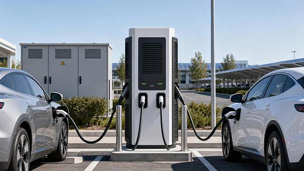
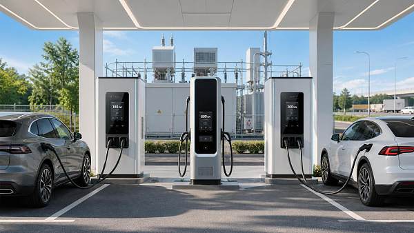
Public charging uses a different rule set. Power sharing between two or more outlets can improve utilization and reduce idle installed capacity, but the displayed charging expectations must remain clear. A driver expecting a dedicated high-power session will see a different result when another vehicle connects to the same power cabinet. Equipment specifications should identify whether output is fixed per connector, dynamically shared, or constrained by a site-level limit.
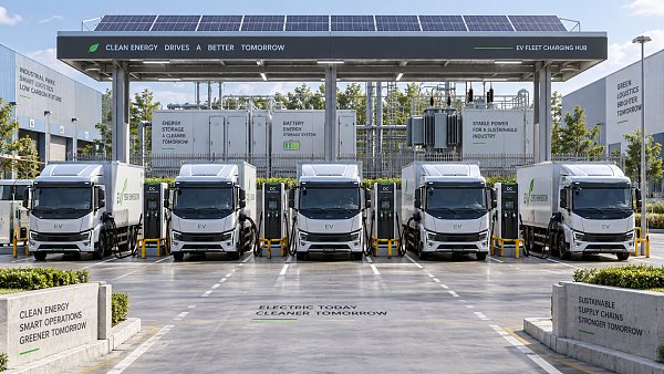
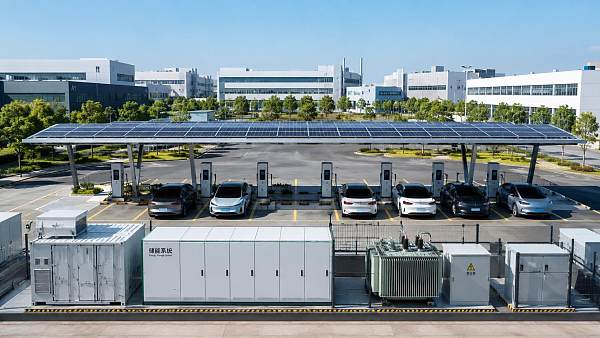
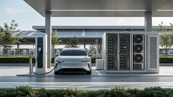
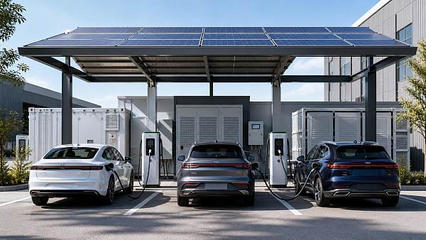
Battery energy storage can be considered where connection expansion is constrained, charging peaks are short, or resilience has operational value. It should not be inserted as a generic answer to limited grid capacity. Storage must be sized around its usable energy, discharge power, recharge window, thermal conditions, control logic, and replacement planning. A battery with adequate power but insufficient energy cannot sustain repeated fast-charging peaks; one with adequate energy but limited power will not support the intended charger output.
Lay out the site for movement, safety, and maintenance
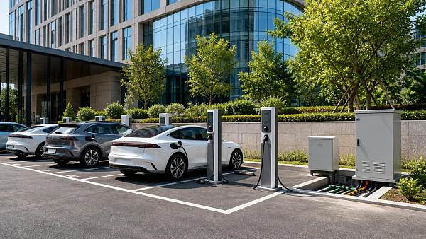
A workable electrical design can still fail on the ground. Vehicle turning paths, door opening, cable reach, wheel stops, bollards, drainage, pedestrian routes, and access for maintenance vehicles must be resolved together. Charger placement that looks efficient on a drawing may force reversing maneuvers, block a loading route, or place cables across a walking path.
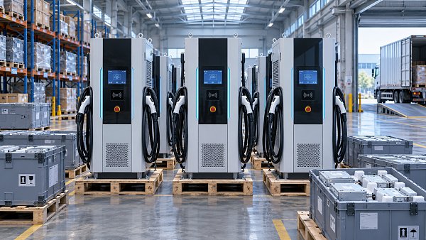
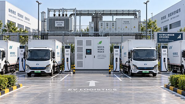
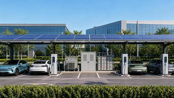
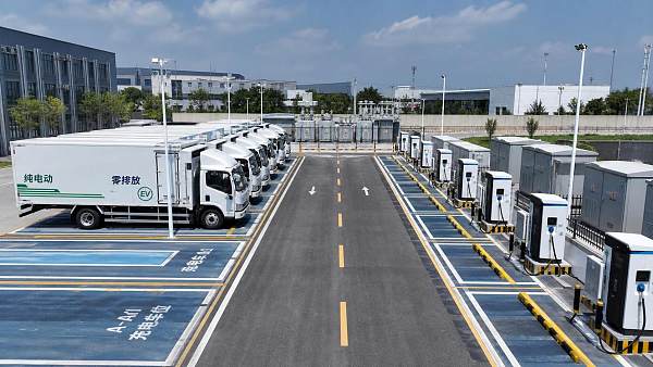
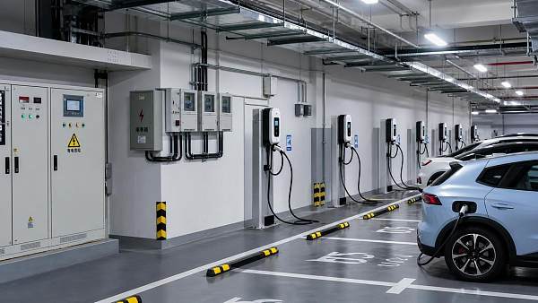
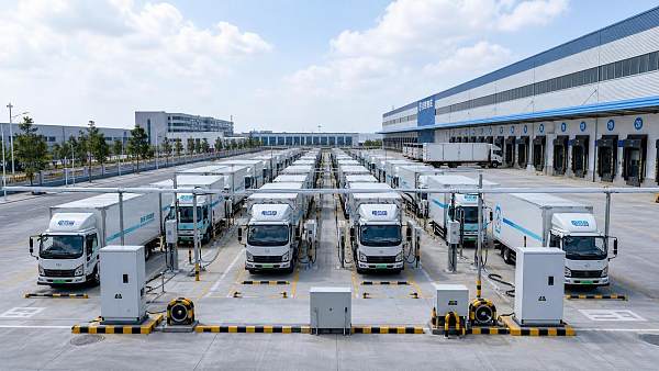
For fleet depots, assign bays according to vehicle parking behavior rather than placing chargers uniformly across all spaces. Vehicles that return late or leave early may need priority positions. Where chargers are mounted on islands or pedestals, allow room for cable handling without obstructing circulation. Overhead cable-management arrangements can reduce ground clutter in suitable covered depots, but their structural support, clearance, inspection access, and vehicle height limits need to be included in the civil scope.
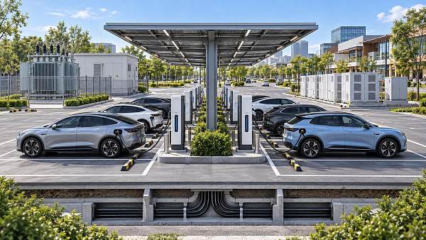
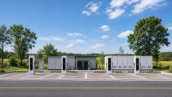
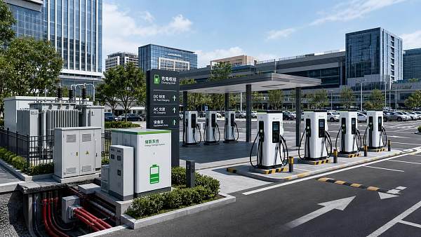
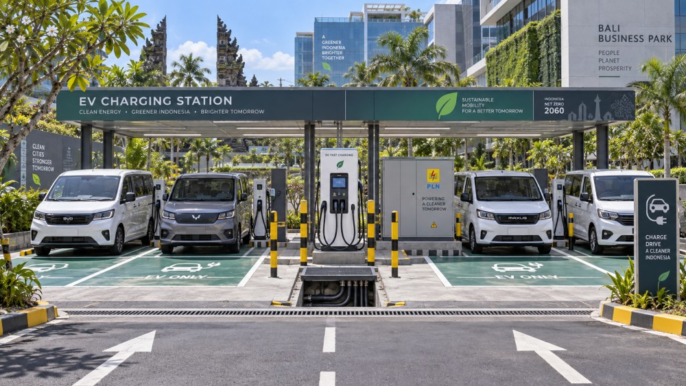
Outdoor public sites need robust foundations, drainage, impact protection, enclosure ratings appropriate to the location, and clear visibility after dark. Water ponding near equipment, poorly routed underground conduits, and unprotected cabinet edges create avoidable maintenance issues. In coastal or high-humidity environments, cabinet materials, coating systems, fasteners, cable glands, and ventilation arrangements should be selected for corrosion exposure rather than treated as minor procurement details.
Plan the future conduits, cable trenches, spare feeder capacity, and physical space during the first civil works phase. Adding chargers later is often less expensive than reopening paved areas, moving drainage, or finding a new transformer route. This does not require purchasing all future chargers at once. It requires preserving the electrical and civil options needed for expansion.
Specify interoperability and commercial functions with precision
Connector compatibility, charging communication, remote monitoring, access control, and payment workflows should be written into the technical requirements. A public site requires a clear method for session initiation, tariff display where applicable, payment confirmation, fault reporting, and support contact. The process must work when a visitor has poor mobile signal, does not hold a local account, or reaches a charger with an unreadable display.
Fleet charging may use restricted access, vehicle identification, driver cards, or back-office authorization. The selected arrangement should connect the charging session to the operational data needed for energy reconciliation and exception handling. A system that records only total station consumption is insufficient when energy must be attributed to separate vehicles, routes, tenants, or internal cost centers.
Require documented interfaces rather than relying on a supplier demonstration. Confirm how the charger exchanges status, meter values, alarms, firmware information, charging limits, and transaction records with the chosen management system. Also establish data ownership, retention, user permissions, remote restart authority, and the procedure if communications are lost. A charger should retain safe local operating behavior during a network outage, but the exact behavior needs to be agreed: continue an active session, permit authorized new sessions, or stop service until connectivity returns.
Commission the whole operating sequence
Factory testing does not prove that a completed site will operate correctly. Site acceptance should test the full sequence from energization to payment or authorization, charging initiation, load allocation, fault response, remote visibility, and meter reconciliation. Test more than one vehicle where possible because compatibility behavior can differ across vehicle models and battery conditions.
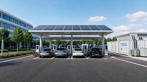
Commissioning should also include loss-of-communications behavior, emergency stop operation, protection trips, restoration after a power interruption, and the response when all charging outlets request power at the same time. These tests reveal whether the installed control logic matches the approved load schedule. They are especially important where charging is integrated with building demand limits, onsite solar generation, or battery storage.
Leave the site with an asset register that identifies each charger, power cabinet, connector, breaker, meter, communications device, and cable route. Include single-line diagrams, protection settings, equipment manuals, software access records, warranty terms, spare-part references, and tested emergency procedures. This documentation reduces the time needed to isolate a fault and prevents later modifications from exceeding the original electrical design.
Design maintenance into the operating model
Availability depends on routine inspection, remote alarm handling, replacement lead times, and physical access to equipment. DC chargers have cooling components, contactors, power modules, cable assemblies, connector locks, displays, and communications hardware that require planned attention. Public equipment also experiences greater wear at connectors and cable supports because handling conditions are less controlled.
Define fault categories before operations begin. A connector latch issue, an unavailable payment terminal, a thermal derating alarm, and a complete power cabinet failure do not have the same operational consequence or response time. The maintenance agreement should identify remote diagnostic capability, on-site escalation, supported spare parts, firmware update control, and the approval process for configuration changes.
Charging infrastructure planning in Indonesia is strongest when expansion is treated as an operational design choice, not a promise to install larger equipment later. Establish the first-stage energy demand, grid limit, layout reserve, and management rules with enough discipline that each additional charger can be added without undermining the site's power quality, vehicle availability, or daily workflow.
Questions about market trends? Contact Market Scope Live for deeper business insights.
We respect your privacy. Your information is strictly confidential.
Related News
 EV Charging InfrastructureIndian Minister Proposes Lower EV Charging Rates to Encourage AdoptionIndia EV charging rates could fall in Maharashtra under Nitin Gadkari’s proposal. Explore the potential impact on drivers, fleets and charging operators.MORE+
 EV Charging InfrastructureEV Charging for Industrial Parks: Sizing Capacity and Managing Peak LoadsPlan industrial parks EV charging with confidence. Learn how to size capacity, manage peak loads, reduce demand costs, and keep fleets ready without disrupting production.MORE+
 EV Charging InfrastructureArlington County, Virginia, to Raise Public EV Charging Rates by 72%Arlington County public EV charging rates will rise 72% to $0.30/kWh on November 1, 2026. Explore the potential impact on fleet budgets and how businesses can prepare.MORE+
 EV Charging InfrastructurePlanning Solar EV Charging Hubs: Sizing PV, Battery Storage, and Grid CapacityPlan solar EV charging hubs with confidence. Learn how to size PV, battery storage, and grid capacity to meet peak demand, control costs, and support reliable charging.MORE+
 EV Charging InfrastructureChery Unveils 1.44 MW Charging System, Claims 500 km of Range in Five MinutesChery’s 1.44 MW charging system claims 500 km of range in five minutes. Explore its ultrafast EV charging technology, vehicle compatibility and global rollout plans.MORE+
 EV Charging InfrastructureComparing EV Charging Equipment Manufacturers: Warranty, Lead Times, and SupportCompare EV charging equipment manufacturers on warranty coverage, lead times, and support. Discover how to reduce downtime, uncover hidden costs, and choose the right supplier.MORE+
 EV Charging InfrastructurePlanning Urban EV Charging Hubs: Site Selection, Power Needs, and Charger MixPlan urban EV charging hubs with confidence. Discover how to select sites, size power capacity, and balance AC/DC chargers to control costs and deliver reliable charging.MORE+
 EV Charging InfrastructureHow to Plan Charging Corridors for Fleet Routes, Grid Capacity, and Future DemandCharging corridor infrastructure planning helps fleets align routes, grid capacity, reliable charging, and scalable site design for future demand.MORE+
 EV Charging InfrastructureHow to Size Fast EV Charging Equipment for Fleet Depots Without OverbuildingFast EV charging equipment for fleet depots: learn how to match power, charging windows, grid capacity, and smart controls without costly overbuilding.MORE+
 EV Charging InfrastructureHow to Plan EV Charging Infrastructure in Indonesia for Fleet and Public SitesCharging infrastructure planning in Indonesia for fleet and public sites: optimize energy, grid capacity, smart load management, safety, and scalable EV charging.MORE+
 EV Charging InfrastructureHow to Size DC EV Charging Equipment for Fleet Depots and Peak DemandDC EV charging equipment sizing guide for fleet depots: balance energy demand, peak loads, utility limits, smart charging, and scalable growth.MORE+
 EV Charging InfrastructureAre EV Charger Payment Systems Interoperable Across Regions?Are there interoperability standards for EV charger payment systems across regions? Explore OCPP, OCPI, Plug & Charge, roaming, and payment strategies for seamless EV charging.MORE+
 EV Charging InfrastructureHow to Evaluate Total Cost of Ownership for a Fleet DC Charging DepotHow to evaluate total cost of ownership for a fleet DC charging depot: compare grid costs, tariffs, uptime, smart charging, and scalable infrastructure.MORE+
 EV Charging InfrastructurePublic Charging Infrastructure Planning: Site Criteria, Grid Capacity, and UtilizationPublic charging infrastructure planning made practical: evaluate site access, grid capacity, utilization, and scalable design to build reliable, investable EV charging hubs.MORE+
 EV Charging InfrastructureHow Behind-the-Meter Energy Systems for EV Charging Cut Peak-Demand CostsBehind the meter energy systems for EV charging help cut peak-demand costs, defer grid upgrades, and improve charging reliability with storage and smart controls.MORE+
 EV Charging InfrastructureIs Building a Public EV Charging Network in Rural Areas Financially Viable?Is it financially viable to build public charging networks in rural areas? Explore grid costs, utilization, funding, AC/DC choices, and strategies for profitable rural EV charging.MORE+
 EV Charging InfrastructureHow Public EV Charging Load Management Prevents Peak Demand and Grid Overloadspublic EV charging load management prevents costly peak demand and grid overloads. Explore smarter controls, capacity planning, and scalable charging performance.MORE+
 EV Charging InfrastructureHow to Assess Long-Term EV Charger Reliability Before ProcurementHow to evaluate long-term reliability of EV chargers before procurement? Explore practical checks for uptime, grid compatibility, software stability, service support, and lifecycle costs.MORE+
 EV Charging InfrastructureIs AC Charging Still Worth Investing in for New Public Stations in 2026?Is AC charging still worth investing in for new public stations in 2026? Explore where smart, managed AC charging delivers value, revenue, and scalable EV infrastructure.MORE+
 EV Charging InfrastructureHow to Plan Power Capacity for Highway EV Charging CorridorsHighway charging corridor power capacity planning: learn how to size grid connections, manage peak demand, use storage, and phase EV hubs for reliable, scalable growth.MORE+
 EV Charging InfrastructureWhat Is the Typical BMS Failure Rate in EV Charging Equipment?Battery management system failure rate in charging equipment: learn what BMS faults mean, key risks, and how to protect EV charger uptime.MORE+
 EV Charging InfrastructureHow Should Fleet Depot Charging Stations Be Laid Out?Fleet depot charging station layout design guidelines for safer vehicle flow, smart power use, scalable infrastructure, and reliable fleet readiness. Explore practical planning tips.MORE+
 EV Charging InfrastructureDC Fast Chargers vs Liquid-Cooled Ultra-Fast Chargers in 2026DC fast charger vs liquid-cooled ultra-fast charging stations 2026: compare power, costs, grid demands, uptime, and ideal deployment scenarios for smarter EV infrastructure.MORE+
 EV Charging InfrastructureWhat Does the Global EcoPower Charging Intelligence Platform Do?Global EcoPower EV charging infrastructure intelligence platform delivers actionable insights on grid capacity, storage, technology, risk, and profitable charging project planning.MORE+
 EV Charging InfrastructureHow Global EcoPower Manages Energy Across EV Charging NetworksGlobal EcoPower energy management systems for charging networks optimize EV charging with dynamic load control, storage, solar integration, and reliable data insights.MORE+
 EV Charging InfrastructureWhat Switchgear Specifications Are Needed for a 500 kW Charging Site?What switchgear specifications are required for a 500kW charging installation? Explore load sizing, transformer selection, fault ratings, protection, and expansion planning.MORE+
 EV Charging InfrastructureWhich Communication Protocols Matter When Mixing Charger Brands?What communication protocols matter most when mixing charger brands at one station? Explore OCPP, OCPI, ISO 15118, and energy controls for reliable interoperability.MORE+
 EV Charging InfrastructureWhat Grid Connection Capacity Does a 10-Bay Fast Charging Hub Need?What grid connection capacity is needed for a 10-bay fast charging hub? Explore demand, power sharing, batteries, and scalable planning for reliable EV charging.MORE+
 EV Charging InfrastructureHow to Plan EV Charging Systems for Apartments Without Overloading the Building?EV charging systems for apartments start with capacity, not charger count. Learn how to prevent overloads, use smart load management, and plan scalable charging that fits your building.MORE+
 EV Charging InfrastructureHow City Charging Infrastructure Planning Can Reduce Costs and Avoid Grid BottlenecksCharging infrastructure planning for cities helps cut costs, avoid grid bottlenecks, and speed EV rollout with smarter, scalable deployment.MORE+
 EV Charging InfrastructureEU Mandates EN 61851-23:2026 for EV ChargersEU Mandates EN 61851-23:2026 for EV Chargers: learn how the new EU rule impacts certification, customs clearance, and market access before October 2026.MORE+
 EV Charging InfrastructureITC Ruling Puts Chinese EV Chargers Under 337 PressureITC ruling on Chinese EV chargers puts Section 337 pressure on imports, compliance, and OEM supply chains. Learn how patent risks may impact U.S. customs, distributors, and EV charger sourcing.MORE+
 EV Charging InfrastructureHow EV Charging Technology Affects Charging Speed, Compatibility, and Site PlanningEV charging technology shapes real charging speed, vehicle compatibility, and site planning. Learn how to avoid costly design mistakes and build charging projects that perform.MORE+
 EV Charging InfrastructureUS Requires UL 1741 SA-2025 EVSE ModulesUS Requires UL 1741 SA-2025 EVSE Modules for imported DC fast chargers. Learn how V2G, FCC+UL testing, and firmware compliance will reshape US market access.MORE+
 EV Charging InfrastructureUSTR Opens Section 301 Review on China EV ChargersUSTR Opens Section 301 Review on China EV Chargers: learn how the 25% tariff review may affect import costs, customs compliance, and procurement timing across EV charging and BESS supply chains.MORE+
 EV Charging InfrastructureHow to Plan Fleet Charging Infrastructure for Logistics Depots and Delivery HubsFleet charging infrastructure for logistics starts with duty cycles, dwell time, and grid limits. Learn how to design depot and hub charging that cuts bottlenecks and supports scalable fleet electrification.MORE+
 EV Charging InfrastructureWhat Is Load Management in EV Charging and How Does It Reduce Peak Power Costs?Load management in EV charging helps control peak demand, lower grid upgrade pressure, and cut costly power spikes. Learn how smart power allocation improves site economics.MORE+
 EV Charging InfrastructureHow to Evaluate an EV Charging Software Platform for Multi-Site Charging OperationsEV charging software platform evaluation made practical: learn how to assess interoperability, load management, billing, security, and scalability for multi-site charging operations.MORE+
 EV Charging InfrastructureUSTR Opens 301 Review on China EV Charging GearUSTR opens a Section 301 review on China EV charging gear, putting tariffs, import costs, pricing, and inventory plans at risk. See what US importers and distributors should watch now.MORE+
 EV Charging InfrastructureEU Sets 17.1% Duty on Chinese EV ChargersEU Sets 17.1% Duty on Chinese EV Chargers: see how the new EU tariff affects EV charging equipment exports, customs costs, HS codes, and contract risks for suppliers.MORE+