
How Should Fleet Depot Charging Stations Be Laid Out?
Effective fleet depot charging station layout design guidelines are essential for keeping electric fleets productive, safe, and cost-efficient across daily operations and future expansion.
A successful depot layout is not simply a parking plan with chargers added later. It must connect vehicle movements, charging windows, grid capacity, safety rules, maintenance access, and operational priorities.
For fleet operators, developers, EPC contractors, and procurement teams, the central question is practical: how can every vehicle receive the required energy without creating congestion, costly infrastructure upgrades, or downtime?
The strongest answer begins with fleet duty cycles rather than charger quantities. A depot should be designed around when vehicles arrive, how long they remain parked, and when they must depart.
This approach changes the investment discussion. Instead of installing maximum charging power everywhere, teams can match charging hardware, electrical capacity, and parking geometry to actual fleet availability.
Fleet depot charging station layout design guidelines should therefore support three outcomes: dependable vehicle readiness, safe and efficient depot operations, and a phased path for fleet electrification growth.
What Decision-Makers Need to Establish First
Before producing civil drawings, project teams should define the fleet’s operational baseline. Vehicle types, route distances, payloads, battery sizes, arrival patterns, and overnight dwell times determine the layout.
Mixed fleets require particular care. Delivery vans, rigid trucks, articulated vehicles, buses, and service vehicles have different turning radii, connector locations, parking durations, and charging energy requirements.
Operators should also identify critical vehicles. A depot may contain reserve units, high-utilization vehicles, and mission-critical routes that need prioritized access to dependable charging capacity every day.
Charging demand should be modelled by shift rather than estimated from fleet size alone. Two fleets with identical vehicle counts can need materially different power capacity and charger placement.
For example, a fleet returning gradually across eight hours can use managed overnight charging. A fleet returning simultaneously may require higher power, additional charge points, or staggered dispatch planning.
Early analysis should include future fleet conversion plans. Building for current operations only can force expensive excavation, switchgear replacement, and parking reconfiguration when electric vehicle numbers increase.
A clear design brief should state the expected fleet size at commissioning, the target size after several years, peak charging periods, required vehicle availability, and permitted operational constraints.
Start With Vehicle Flow, Parking Geometry, and Charger Access
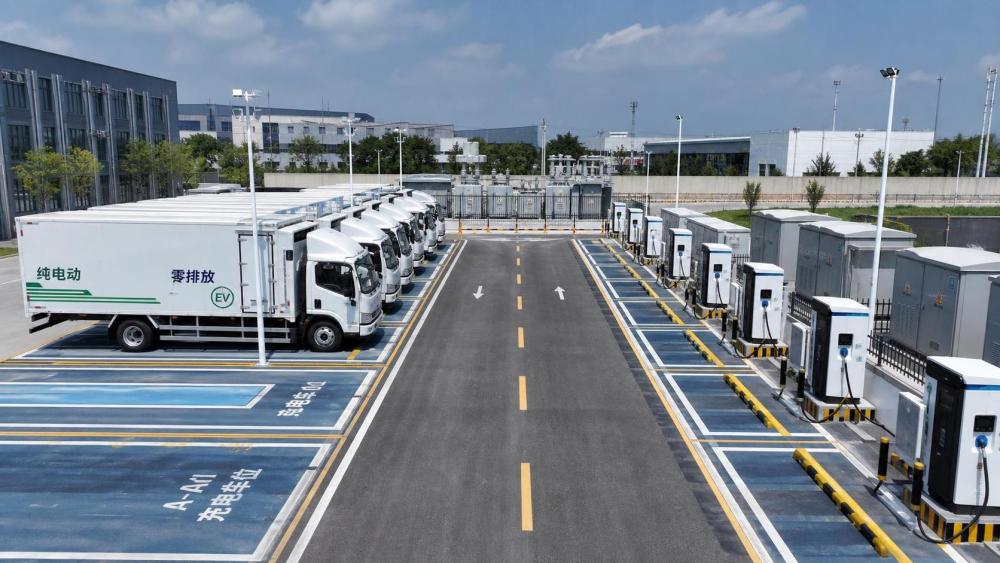
The physical layout should protect normal depot operations first. Charging equipment must support vehicle circulation rather than create bottlenecks at entry gates, loading areas, wash bays, workshops, or dispatch lanes.
Map every movement through the site, including arrival, inspections, parking, charging, loading, fueling alternatives, cleaning, maintenance, and departure. This reveals conflicts that standard parking drawings often miss.
One-way circulation is usually easier to manage for larger commercial vehicles. It reduces reversing movements, improves safety visibility, and can simplify the location of chargers, cable systems, and protective barriers.
Parking bay dimensions must reflect the actual vehicle envelope, mirrors, doors, tail lifts, and driver access. A space that fits a vehicle on paper may be impractical during night operations.
Charging equipment should be positioned according to connector location and cable reach. Rear-mounted, side-mounted, and front-mounted charging ports can produce very different bay arrangements and driver procedures.
For buses and trucks, drive-through bays can reduce reversing and improve turnaround efficiency. They typically need more land but may offer safer operations for high-frequency or daytime opportunity charging.
Angle parking can increase density, while perpendicular parking may simplify charger alignment. The correct choice depends on vehicle dimensions, circulation routes, turning templates, and the required charging dwell period.
Do not assume each parking space needs a dedicated high-power charger. In many depots, shared charging cabinets with multiple dispensers can improve capital efficiency while preserving adequate operational resilience.
However, shared systems need clear parking discipline. If a charged vehicle blocks access to a dispenser, the electrical design may be sufficient while the operational design still fails.
Separate charging zones from high-conflict activities where possible. Loading docks, pedestrian entrances, workshops, and refueling areas can introduce traffic, safety, and access risks that complicate charging operations.
Size Electrical Infrastructure for Operations, Not Nameplate Capacity
Grid connection capacity is often the defining constraint for depot electrification. The available utility supply, connection timeline, transformer requirements, and tariff structure should be investigated at the earliest stage.
Adding every charger’s rated power produces an unrealistic peak demand figure. Fleet charging stations rarely operate at maximum output simultaneously when managed charging is properly implemented.
Instead, build a charging load model using route energy consumption, battery state of charge, arrival times, departure deadlines, ambient conditions, and the fleet’s acceptable operating reserve.
Smart load management can allocate power dynamically among vehicles. It enables a depot to meet departure requirements while limiting demand peaks and making better use of a constrained grid connection.
Priority logic should be transparent. Vehicles with early departures, low battery levels, long routes, or critical assignments should receive energy before reserve units or vehicles with extended dwell periods.
Electrical equipment needs room for maintenance and expansion. Transformers, switchgear, distribution boards, power cabinets, communications equipment, and protection systems should not be installed at their absolute spatial limit.
Designers should reserve routes for future ducts, cable trenches, and communications conduits. Installing oversized or additional pathways early is usually less expensive than reopening finished pavement later.
Voltage level selection matters for larger depots. Medium-voltage connections can be appropriate where charging demand is high, but they require specialized equipment, utility coordination, protection studies, and maintenance planning.
Power quality, harmonics, fault levels, earthing, and protection coordination should be reviewed by qualified electrical engineers. These issues affect system reliability, compliance, and the ability to add chargers safely.
Projects should also evaluate on-site generation and battery storage realistically. Solar and storage can reduce energy costs or demand peaks, but they do not remove the need for robust fleet charging design.
Choose Charger Types Around Dwell Time and Fleet Duty Cycles
Charger selection should follow operational need. The highest-rated charger is not automatically the best choice when vehicles remain at the depot for many hours overnight.
AC charging can suit vans, light-duty vehicles, and long dwell periods. It often lowers equipment costs, although vehicle onboard charger limits must be checked before finalizing the design.
DC charging is commonly required for buses, medium-duty trucks, and fleets with limited turnaround windows. It provides higher energy transfer but increases electrical infrastructure, equipment, and cooling requirements.
High-power or ultra-fast charging is best reserved for genuine operational needs. Using it across every bay can raise capital costs, utility demand charges, and thermal stress without improving fleet productivity.
Consider centralized power cabinets with distributed dispensers for larger DC installations. This architecture can improve utilization, simplify power sharing, and reduce the amount of power electronics at each parking space.
Connector standards must match the regional vehicle market and future procurement strategy. Fleet operators should avoid creating a depot that supports only a narrow group of current vehicle models.
Cable management deserves detailed attention. Cables must be reachable without crossing vehicle paths, creating trip hazards, obstructing doors, or requiring drivers to handle excessive weight or awkward reach.
Overhead cable systems, cable reels, pedestal units, and side-mounted dispensers each have different advantages. The best option depends on vehicle dimensions, weather exposure, site clearance, and maintenance practices.
Include a practical redundancy strategy. A depot does not need one spare charger for every installed unit, but it needs enough alternative capacity to absorb equipment faults and schedule variation.
Build Safety, Maintenance, and Resilience Into the Physical Design
Charging zones should have clear pedestrian separation. Marked walkways, barriers, lighting, crossing points, and exclusion areas reduce the risk of drivers, technicians, and visitors entering vehicle movement paths.
Protect chargers, dispensers, and cabinets from accidental vehicle impact. Bollards, wheel stops, curbs, and equipment setbacks should be designed without blocking connector access or emergency maintenance space.
Fire safety planning should consider vehicle type, battery chemistry, local codes, emergency access, drainage, detection, isolation procedures, and coordination with local fire authorities before construction begins.
Emergency shut-off devices must be visible, accessible, and clearly integrated into operating procedures. Staff need training on when to isolate charging equipment and how to report faults safely.
Weather exposure affects both equipment selection and daily usability. Canopies may improve driver comfort, protect connectors, reduce water ingress risks, and support lighting or rooftop solar installations.
Maintenance access must remain available when the depot is fully occupied. Engineers need safe routes to cabinets, transformers, switchgear, communication equipment, and charger components without moving multiple vehicles.
Remote monitoring should be included from the start. Operators need visibility into charger status, charging sessions, fault codes, energy use, load management performance, and vehicle readiness before dispatch.
Cybersecurity is also a physical infrastructure concern. Segmented networks, secure remote access, software update processes, and vendor support responsibilities should be defined for connected charging assets.
Resilience planning may include backup power for critical systems, alternative charging arrangements, manual operating procedures, and contractual service levels for charger repairs and replacement parts.
Plan Expansion in Phases Without Disrupting the Depot
A phased deployment strategy balances capital discipline with future readiness. It allows fleets to begin electrification while avoiding investment in idle chargers before vehicle deliveries and routes are confirmed.
Phase one should include enough charging capacity for the initial fleet, plus electrical and civil foundations that make later phases faster, cheaper, and less disruptive.
Future-ready provisions can include empty conduits, spare breaker capacity, transformer space, reserved equipment pads, larger cable trenches, and parking areas configured for later charger installation.
Document the assumptions behind each expansion phase. Future teams need to understand planned fleet growth, load diversity, utility capacity, equipment compatibility, and the operational changes that trigger investment.
Procurement contracts should address interoperability and expansion. Proprietary systems may appear convenient initially, but they can limit equipment choices, software integration, maintenance options, and competitive pricing later.
Consider construction sequencing carefully. Civil works, grid works, charger installation, commissioning, driver training, and fleet vehicle delivery should be coordinated to avoid an operational gap at launch.
Temporary charging solutions can support early fleet deployment, but they should not become a substitute for permanent design. Temporary equipment often introduces operational complexity and limited long-term scalability.
Track actual charging behavior after commissioning. Real operating data can refine load management settings, reveal parking conflicts, improve route planning, and validate the timing of the next expansion phase.
Use a Cross-Functional Review Before Finalizing the Layout
The best depot designs are produced by cross-functional teams. Fleet operations, electrical engineering, civil engineering, safety, IT, facilities, finance, and vehicle suppliers each identify different risks.
Operations teams should validate the proposed layout with realistic arrival and departure scenarios. A drawing review is useful, but a simulation of peak activity often exposes overlooked constraints.
Finance teams should compare total cost of ownership, not simply charger purchase prices. Grid upgrades, civil works, demand charges, maintenance, downtime risk, and expansion costs materially affect project economics.
Vehicle manufacturers should confirm charging compatibility, battery limitations, connector placement, charging curves, and any operational requirements that affect parking design or charging management settings.
Utilities need early engagement because connection studies and upgrades can drive the critical path. Their requirements may influence transformer location, metering design, protection systems, and construction sequencing.
EPC contractors should review constructability before procurement. Access for cranes, trenching, electrical installation, equipment delivery, and commissioning can affect cost, schedule, safety, and final equipment placement.
A structured design review should test normal operation, peak return periods, charger faults, late arrivals, emergency access, severe weather, and the addition of future electric vehicles.
Conclusion: A Good Layout Makes Charging an Operational Asset
Fleet depot charging station layout design guidelines are most effective when they begin with vehicles and operations, then translate those realities into parking, electrical, safety, and control system decisions.
The core principle is straightforward: design for dependable departures, not maximum charger count. Vehicle flow, dwell time, power sharing, maintenance access, and expansion readiness must work together.
For operators and project developers, the greatest risk is treating charging as a standalone equipment purchase. Depot charging is a long-term energy and operational infrastructure system.
A well-designed depot reduces avoidable grid costs, protects fleet availability, improves safety, and creates a credible route to larger-scale electrification as commercial vehicle technologies and charging needs evolve.