
A turbine that stops on a high-wind day rarely fails for just one obvious reason. The controller may report a gearbox temperature alarm, a yaw fault, a generator trip, or an intermittent communication loss, while the initiating defect is a worn connector, restricted cooling path, loose coupling, or lubrication problem inside the nacelle. By the time a service team reaches the unit, the original symptom may have disappeared or been masked by a protective shutdown.
The fastest way to reduce unplanned downtime is to troubleshoot nacelle wind turbine parts in a disciplined sequence: secure the turbine, capture the fault history, verify the operating conditions when the alarm occurred, then inspect the components most directly connected to that alarm before replacing parts. Treating every trip as an isolated electrical fault often leads to unnecessary swaps and repeat callouts. A nacelle fault should be assessed as a mechanical, electrical, thermal, lubrication, and control-system event until evidence narrows the cause.
Start with the shutdown record, not the component suspected on arrival
Before opening cabinets or removing guards, review the event log, SCADA trend data, recent resets, and work completed since the last normal operating period. Record alarm codes, timestamps, wind speed, ambient temperature, power output, rotor speed, yaw position, gearbox oil temperature, generator temperature, and converter status where available. A fault that appears only during high output points in a different direction from one that occurs during startup, low-temperature operation, or yaw movement.
Also check whether the turbine stopped because of a primary fault or because one protection function triggered another. For example, a converter trip can result in an emergency stop, followed by hydraulic pressure changes and brake-related alarms. Replacing a brake pressure switch without confirming the first event may leave the actual converter cooling or grid-side issue untouched.
A useful first distinction is whether the fault is:
- Persistent: the alarm returns immediately after reset or during a static test.
- Load-dependent: it appears at a certain power level, speed, temperature, or yaw load.
- Intermittent: it occurs without a clear pattern and may be linked to vibration, moisture, cable movement, or unstable feedback.
- Progressive: a monitored value has been drifting toward a trip threshold over days or weeks.
This classification prevents a common maintenance error: testing a component only while the turbine is stopped, declaring it healthy, and missing a defect that develops only under vibration, heat, torque, or electrical load.
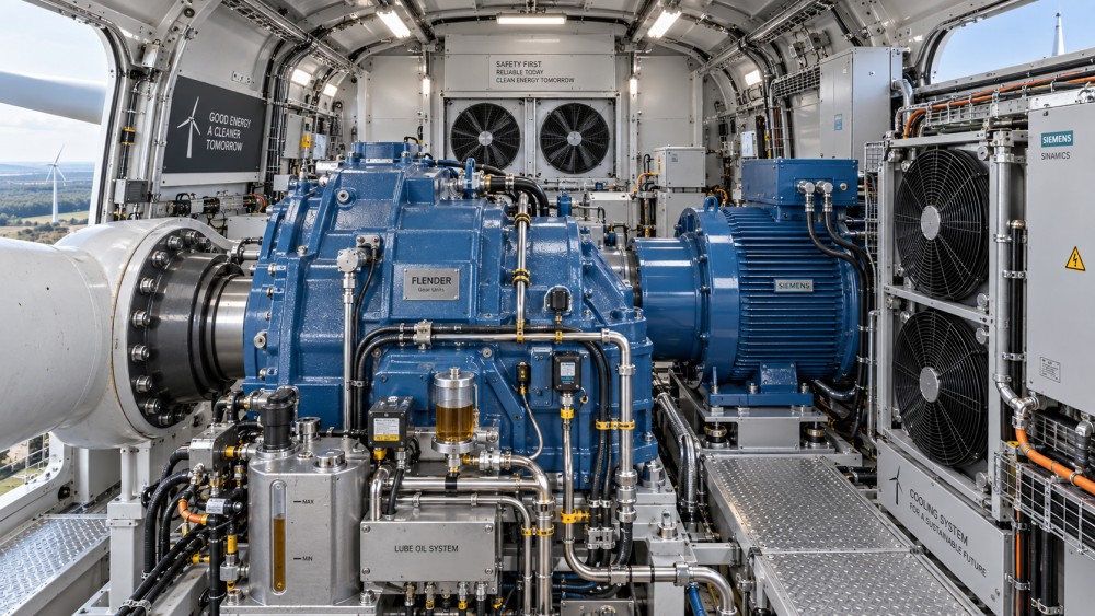
When gearbox and drivetrain alarms are the visible problem
Gearbox-related shutdowns demand caution because continued operation after a genuine lubrication or bearing fault can create extensive secondary damage. However, an elevated gearbox temperature does not automatically mean the gearbox itself has failed. Begin by comparing temperature signals with oil level, oil condition, cooling operation, ambient conditions, and actual turbine load.
High oil temperature with normal-looking oil level
Check the cooling circuit before assuming internal gear damage. Inspect cooler surfaces for contamination, verify fan rotation and airflow direction, examine coolant or oil lines for restrictions, and confirm that thermostatic valves are opening as intended. A failed cooling fan contactor, damaged fan blade, blocked heat exchanger, or sensor reading that drifts high can all create a temperature-related shutdown.
Next, compare redundant or related measurements where the turbine design provides them. An oil temperature that rises sharply while bearing temperatures remain stable may indicate a sensor, wiring, or local flow issue. In contrast, increasing oil temperature accompanied by rising high-speed shaft or gearbox bearing temperatures deserves more urgent investigation. Listen for unusual tonal noise during permitted low-speed operation, and inspect vibration trends if condition-monitoring data is available.
Low oil pressure or repeated lubrication alarms
Do not reset repeated low-pressure alarms until the oil system has been checked for level, leaks, filter restriction, pump function, suction-side air ingress, and correct valve position. A blocked filter can produce a pressure differential problem even when the reservoir level appears acceptable. Fine metallic debris in filters or magnetic plugs should be documented and evaluated rather than discarded; it may be evidence of internal wear.
Verify that the pressure transmitter and its wiring are not creating a false trip. Intermittent readings can result from a loose plug, damaged cable insulation near moving sections, contaminated connector pins, or poor grounding. Yet a sensor fault should only be concluded after mechanical pressure has been independently verified using the approved measurement method for that turbine model.
Couplings, mounts, and brake-side components
Drivetrain vibration is sometimes blamed on the gearbox when the problem lies at a coupling, torque arm, generator mount, or brake assembly. Look for loose fasteners, displaced witness marks, fretting dust, damaged elastomer elements, oil contamination around coupling areas, and abnormal movement under controlled conditions. A coupling that has begun to degrade can introduce vibration that later appears as generator bearing, gearbox, or speed-sensor trouble.
Never rely on visual alignment alone after a major drivetrain intervention. Alignment, bolt torque, backlash-related settings, and brake clearances must follow the manufacturer’s service procedure. Small installation errors can become load-dependent faults that are difficult to identify from the alarm log alone.
Generator and converter trips: separate electrical symptoms from thermal causes
A generator overtemperature or converter fault can be caused by an electrical defect, but air handling and contamination are frequent contributors inside the nacelle. Restricted filters, failed fans, blocked ducts, loose thermal contacts, and heat exchanger fouling reduce cooling margin. These issues may only become visible during high production, when component temperatures rise faster than the system can dissipate heat.
Inspect cooling paths methodically. Confirm that cabinet doors and seals are intact, filters are installed correctly, fans start when commanded, and airflow is not bypassing the intended route. Dust deposits on heatsinks and moisture around electrical enclosures require attention because they can impair heat transfer and increase the risk of tracking or corrosion. Cleaning must be performed using methods approved for the equipment; compressed air used carelessly can push debris deeper into sensitive assemblies.
Electrical connections should be inspected for discoloration, heat damage, looseness, corrosion, and signs of arcing. A high-resistance connection can heat under load yet pass a basic continuity check when de-energized. Use only authorized test procedures and observe isolation requirements. Where thermal inspection is permitted, it can help identify abnormal connection heating, but any finding should be correlated with load, access conditions, and physical inspection.
Generator speed feedback deserves special attention when a turbine produces erratic speed-related alarms, poor synchronization, or sudden control trips. Check sensor mounting, air gap where applicable, cable shielding, connector engagement, and contamination on sensing surfaces. Replacing a speed sensor without checking its target wheel, mounting rigidity, or cable path can lead to the same fault returning during operation.
Yaw faults often begin as small resistance or feedback problems
Yaw systems operate intermittently, so developing faults may stay hidden until the turbine needs to track changing wind direction. A yaw error can reduce energy capture before it causes a complete shutdown, especially when the turbine remains operational but cannot correct its nacelle position accurately.
When a yaw alarm appears, first determine whether the nacelle failed to move, moved but did not reach position, or moved while the control system received unreliable position feedback. Examine yaw drive motors, gearboxes, brakes, pinion engagement, lubrication points, ring gear condition, and relevant limit or position sensors. Check for unusual noise, uneven movement, oil leakage, worn gear teeth, and brake drag.
Electrical checks should include motor supply, contactors or drives, overload status, brake release circuits, encoder or resolver signals, and cable condition. A motor may be mechanically sound but unable to start because a brake is not releasing. Conversely, a motor that starts but trips on overload may be fighting excessive mechanical resistance. Repeatedly overriding a yaw protection device to force movement can damage the drive train and should not be used as a substitute for identifying the binding source.
Hydraulic faults need a clean distinction between pressure loss and control loss
Hydraulic systems in the nacelle can support braking, pitch-related functions depending on turbine design, and other actuated equipment. Low pressure, slow response, or pressure instability may arise from fluid level, leaks, accumulator condition, pump wear, valve malfunction, filter blockage, or faulty pressure feedback. The alarm alone does not identify which one.
Inspect the reservoir level and fluid condition first, then look for external leaks at hoses, fittings, manifolds, cylinders, and seals. A clean-looking nacelle floor does not rule out a leak; some losses occur inside guards, drip trays, or enclosed components. Check filter indicators and confirm pump operation. Pressure behavior is informative: pressure that never builds suggests pump, suction, relief-valve, or major leakage issues; pressure that builds but decays can point toward internal leakage, accumulator performance, or valve sealing problems.
Because stored hydraulic energy can remain after shutdown, depressurization and lockout procedures are essential before disconnecting lines or working on actuators. Replacing a pressure switch because its reading looks inconsistent is risky unless the actual system pressure has been verified independently.
Intermittent faults: inspect wiring as a moving mechanical system
Inside a nacelle, cables are exposed to vibration, temperature cycling, movement, oil mist, and moisture. Intermittent controller, sensor, communication, and safety-chain faults are often traced to wiring damage rather than failed electronic modules. Focus on cable runs near doors, moving frames, yaw interfaces, vibrating machinery, sharp edges, and poorly supported harnesses.
Look for crushed insulation, chafing, stretched conductors, unsupported cable weight, loose shielding terminations, water ingress, and connectors that are partially latched. Check cabinet earth connections and bonding straps as well. A marginal ground may not create a constant fault but can affect signal quality, especially where encoders, communication lines, and power electronics operate nearby.
When reproducing an intermittent issue, use controlled inspections and authorized test routines rather than aggressive cable pulling. Note whether the fault changes with nacelle position, temperature, vibration, door movement, or equipment startup. That relationship is often more valuable than a single resistance reading.
Decide whether the turbine can return to service
A return-to-service decision should be based on the cause of the trip, not simply on whether the alarm can be cleared. A nuisance alarm with confirmed sensor or communication cause may be resolved through repair and functional testing. A lubrication alarm with unexplained debris, abnormal vibration, repeated low pressure, or rising bearing temperatures should be escalated for deeper assessment before normal operation resumes.
Before releasing the turbine, verify that tools and temporary test leads are removed, guards and cabinet seals are restored, affected parameters have not been altered outside approved procedures, and the fault history clearly records the observed condition, tests performed, parts replaced, and remaining concerns. This record matters when a later event needs to be compared with the original behavior.
The most reliable maintenance approach is not the fastest reset. It is the one that links the shutdown signal to operating context, confirms the physical condition of the relevant nacelle wind turbine parts, and avoids returning a developing mechanical or thermal defect to service simply because the controller accepts a restart.