
The nacelle components wind turbine owners should examine most closely are the drivetrain, generator, main bearing, yaw system, cooling circuit, and control and power electronics. Their importance is not simply a matter of how often they trigger alarms. A failure in any of these systems can stop production, create secondary damage, require specialist lifting equipment, or expose a fleet-wide design weakness. Reliability assessment should therefore focus on failure consequence, load path, condition-monitoring coverage, service access, and the supplier's demonstrated repair capability.
A nacelle is often discussed as though it were a collection of separate parts. In operation, it is a tightly connected mechanical and electrical system. Rotor loads travel through the hub, main shaft and bearings into the drivetrain; heat moves through cooling circuits; the controller decides how the turbine responds to wind, grid events, and component limits. A weak link can shorten the useful life of an otherwise robust machine.
The practical question is not “which component fails most?” in isolation. It is “which failure is most likely to reduce availability or create a high-cost intervention at this site?” That answer can differ between a low-wind inland project, a high-turbulence ridge site, and an offshore installation where access windows dominate maintenance economics.
How nacelle components wind turbine reliability are connected
The drivetrain usually deserves the first and deepest review because it carries cyclic, variable, and sometimes poorly aligned loads for years. In geared turbines, the gearbox, high-speed shaft, couplings, generator bearings, lubrication equipment, and generator form a chain. A problem in one element may be recorded elsewhere. For example, elevated generator vibration may originate in a coupling alignment issue; abnormal gearbox temperatures may reflect oil condition, filter restriction, cooling performance, or a developing bearing defect rather than gear damage alone.
That is why evaluating a component only from its warranty period or nominal design rating is risky. Reliability depends on how loads are controlled in real operating conditions, how early deterioration is detected, and whether the machine can be returned to service before a minor defect becomes a major replacement.
The drivetrain: gearbox, shafts, couplings, and lubrication
For geared wind turbines, the gearbox remains one of the highest-consequence nacelle components. It converts low rotor speed to generator speed through multiple gear and bearing stages. Its internal condition is influenced by torque reversals, turbulence, emergency stops, transient grid events, lubrication quality, temperature control, manufacturing tolerances, and the stiffness of surrounding structures.
A gearbox should not be judged only by its stated power rating. During technical review, ask how the design manages planet-bearing loads, what bearing and gear failure modes have been seen in the relevant turbine platform, and whether the lubricant specification, filtration arrangement, and oil sampling program are practical for the operating environment. Cold climate, dust, salt exposure, and long service intervals can each change the risk profile.
Oil debris monitoring and vibration analysis are useful, but neither is a substitute for a disciplined diagnostic process. Sensors can warn of deterioration; they do not correct poor oil cleanliness, inadequate warm-up logic, misalignment, or a recurring design issue. A common mistake is to treat a clean oil report as proof that a gearbox is healthy. Some faults develop without producing an early, unambiguous debris signature. Trend data, load history, vibration spectra, temperature behavior, and inspection findings need to be interpreted together.
Main shafts and couplings deserve similar attention. Shaft alignment is not a one-time commissioning task. Foundation settlement, nacelle frame movement, bearing wear, and thermal expansion can change the operating alignment over time. Flexible couplings can tolerate limited movement, but they are not a cure for persistent misalignment. Coupling wear, unusual noise, or recurring bolt issues should prompt a check of the complete drivetrain geometry rather than a simple part replacement.
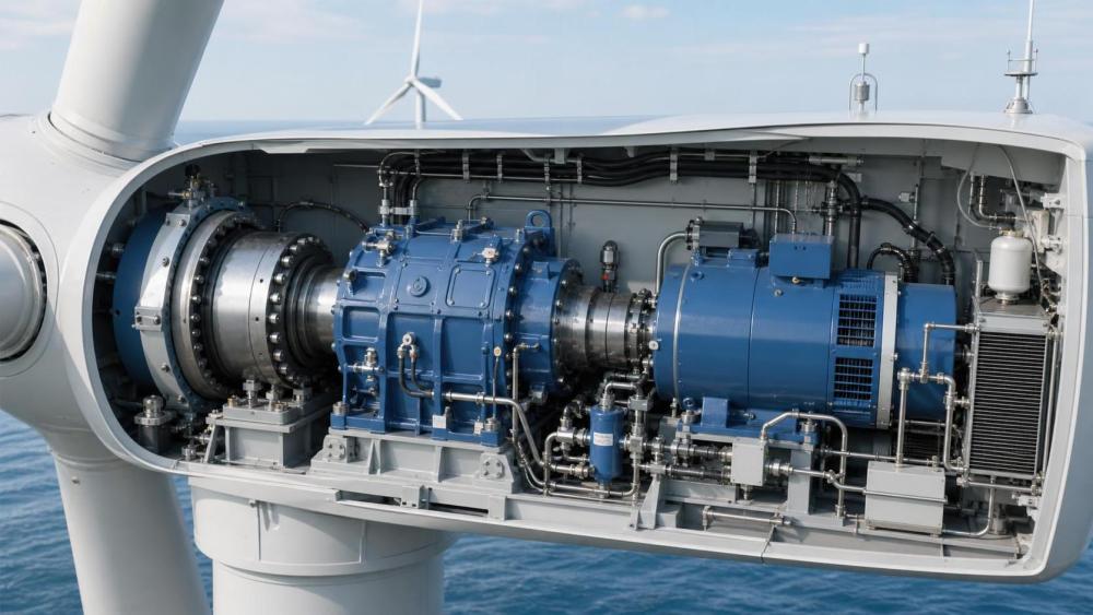
Main bearing condition can determine the whole drivetrain's future
The main bearing sits at a critical point in the load path. It supports the rotor and transfers forces into the nacelle structure. Its reliability is shaped by radial and axial loading, shaft deflection, lubrication, sealing, installation quality, and the turbine's control response to turbulent wind.
Main bearing damage can be especially difficult because the symptoms may emerge slowly and may overlap with signals from other rotating components. Grease condition, vibration trends, temperature, acoustic emissions where available, and periodic inspection all have value. Yet the most useful evidence is often the trend, not a single reading. A modest increase in vibration that progresses under comparable operating conditions deserves more attention than one isolated excursion during an unusual wind event.
Do not assume that a larger bearing automatically means a more reliable bearing. Size affects load capacity, but reliability also depends on internal clearance, raceway stress distribution, seal effectiveness, lubricant delivery, and the actual loads reaching the bearing. Site turbulence and wake conditions matter here. A turbine operating repeatedly in complex terrain or dense wake fields may experience a different duty cycle from the one implied by annual average wind speed alone.
Generator reliability is mechanical, thermal, and electrical
The generator is sometimes assessed as a straightforward electrical machine, but its failure risk crosses several disciplines. Bearing currents, winding insulation aging, cooling effectiveness, rotor balance, converter behavior, and grid disturbances can all influence its condition. In direct-drive turbines, the generator takes on even greater significance because there is no gearbox between the rotor and electrical conversion system. The elimination of a gearbox changes the maintenance profile; it does not remove the need for detailed drivetrain and electrical review.
Generator cooling deserves more scrutiny than it often receives. Restricted airflow, contaminated heat exchangers, failed fans or pumps, poor coolant quality, and inaccurate temperature sensing can accelerate insulation aging or force output derating. A cooling alarm is not necessarily a minor auxiliary-system event. It may be the first visible sign of a condition that will affect generator life.
For generator and converter evaluation, request evidence of how temperature limits are managed, how bearing-current mitigation is implemented, and how fault records distinguish grid-driven trips from component-originated events. Grid conditions are particularly relevant where weak networks, curtailment activity, voltage variation, or frequent fault ride-through events are expected.
The yaw system matters because misalignment quietly reduces output and raises loads
The yaw system turns the nacelle so the rotor faces the wind. Its components include yaw bearings, geared drives, motors, brakes, encoders, cables, and the control logic that decides when to move. A yaw failure can be obvious when the turbine becomes unable to track wind direction, but gradual degradation is more common and easier to overlook.
Excessive yaw misalignment can reduce energy capture and increase asymmetric rotor loading. Repeated small corrections may also indicate poor signal filtering, unsuitable control settings, sensor drift, backlash, or a site condition that the control strategy does not handle well. The corrective action is not always replacing a yaw motor or gearbox.
Inspection should cover bearing lubrication, tooth condition, bolt preload procedures, brake wear, gearbox oil where applicable, and encoder agreement. Ask whether the control system logs yaw error, yaw activity, motor current, and abnormal stop events in a form that can be trended across the fleet. A single turbine with frequent yaw alarms may be a local maintenance issue; the same pattern across many units deserves engineering review.
Cooling, hydraulics, and auxiliary systems are not minor details
Auxiliary systems rarely attract attention during equipment selection because their individual replacement cost can look modest. That can be misleading. Cooling pumps, fans, heat exchangers, filters, heaters, hydraulic power units, lubrication pumps, hoses, valves, and sensors can create repeated downtime and can contribute to damage in more expensive equipment.
Hydraulic systems are particularly relevant in turbines using hydraulic pitch actuation or braking functions. Contaminated fluid, pressure loss, valve sticking, accumulator issues, and hose deterioration can affect safe turbine operation. The risk is operational as well as mechanical: pitch response is central to rotor-speed control during gusts and shutdowns.
Assess maintainability here with unusual care. Can filters be changed without a lengthy outage? Are pumps and sensors accessible in the nacelle? Are leak points visible during normal inspection? Does the supplier provide clear contamination limits and service instructions? Design elegance has limited value when routine tasks are difficult to perform consistently in a confined nacelle.
Controls and power electronics can create availability losses without visible wear
Controllers, sensors, communication hardware, converters, cabinets, relays, power supplies, and software are essential nacelle components even though they do not carry rotor loads. Their failures can be intermittent, difficult to reproduce, and disproportionately disruptive. A faulty wind sensor, encoder, temperature probe, or communication link may cause unnecessary stops, conservative derating, poor yaw behavior, or misleading fault diagnosis.
The power converter also needs a reliability review matched to the grid environment. Semiconductor modules, capacitors, cooling plates, contactors, and control boards are sensitive to heat, cycling, moisture, contamination, and electrical transients. A platform with strong converter diagnostics and clear service records is generally easier to manage than one that reports repeated generic faults with little root-cause detail.
Software should be included in the assessment, but it should not be treated as a universal remedy. Updated control logic can improve load management, fault handling, and operational behavior. It cannot reverse mechanical wear or compensate indefinitely for inadequate cooling and poor sensor quality. Review change-control practices, cybersecurity responsibilities, remote-access arrangements, and the evidence used to validate software updates before fleet deployment.
A practical reliability review should rank consequences, not just alarms
When comparing turbine platforms or investigating an operating fleet, a concise risk register is more useful than a long list of parts. Give each component a score based on likelihood of failure, production impact, safety consequence, repair duration, crane or vessel dependency, spare-part availability, and quality of condition-monitoring evidence.
- High-consequence items: gearbox, main bearing, generator, main shaft, major yaw bearing damage, and large converter failures.
- Availability drivers: cooling equipment, lubrication units, pitch and yaw subcomponents, sensors, communications hardware, and control cabinets.
- Diagnostic priorities: vibration and oil trends for rotating equipment; temperature, flow, pressure, and current data for thermal and auxiliary systems; fault-code quality and event history for controls.
This approach prevents an easy error: prioritizing the component with the highest alarm count while overlooking the one failure that would require a major crane campaign or extended offshore access. It also makes procurement discussions more concrete. Instead of asking a supplier to confirm that the turbine is “reliable,” ask for failure-mode history, corrective-action status, recommended inspection intervals, parts lead times, and evidence that monitoring thresholds are actionable.
Standards and certification documentation remain necessary reference points, including the applicable IEC 61400 design and safety requirements, project-specific grid codes, and local inspection rules. They should be used as a baseline, not as proof that the installed configuration will perform equally well at every site. The final review needs to connect certified design assumptions with wind regime, turbulence, temperature range, grid behavior, maintenance access, and the operator's capability.
Where to focus before selecting or repowering a turbine
For a new project, start with the site load environment and the manufacturer’s platform maturity. A technically advanced turbine may be appropriate, but new configurations can have less long-term operating evidence than an established model. That is not an automatic reason to reject newer equipment; it is a reason to request a clearer risk allocation, monitoring plan, and spare-parts strategy.
For an operating project, begin with data quality. Confirm that turbine status codes distinguish planned downtime, grid curtailment, environmental stops, and component-related outages. Compare similar units under comparable operating conditions. A poor data taxonomy can make a recurring nacelle problem look like normal operational noise.
Industry intelligence resources such as Global EcoPower & Energy Matrix Intelligence Network (EPEM) can help teams place equipment findings alongside grid conditions, project execution risks, and wider renewable-energy market factors. That context is useful when a reliability decision affects not only maintenance budgets but also grid commitments, spare-parts procurement, and long-term asset planning. It should support site evidence and OEM documentation, not replace them.
FAQ
Is the gearbox always the most important nacelle component?
Not always. In a geared turbine it is usually one of the highest-consequence items, but a main bearing, generator, converter, or repeated cooling-system issue may create greater risk for a specific model and site. Direct-drive machines shift the priority toward the generator and associated electrical systems.
Can SCADA data identify nacelle failures early enough?
SCADA data is valuable for spotting abnormal trends, but it is usually not sufficient on its own for rotating-equipment diagnosis. Combine it with vibration analysis, oil or grease evidence, inspection records, fault history, and operating conditions.
Which nacelle system is most often underestimated in technical reviews?
Cooling and auxiliary systems are frequently underestimated. They may be inexpensive to replace individually, yet poor cooling, lubrication, or hydraulic performance can create recurring downtime and accelerate failures in larger assets.
Should a high number of alarms disqualify a turbine platform?
No. Alarm volume must be separated into nuisance alarms, recoverable control events, grid-related trips, and true component failures. The important measures are root cause, recurrence, lost production, repair duration, and whether corrective action has been proven across the fleet.
The most dependable nacelle components wind turbine strategy is therefore a system-level one: verify the drivetrain load path, cooling performance, control quality, service access, and diagnostic coverage together. A robust turbine is not simply a machine with fewer parts. It is a machine whose critical parts can tolerate the site duty cycle, reveal deterioration early, and be maintained with realistic resources before downtime becomes a major asset event.