The Nacelle of a Wind Turbine Explained: Functions, Layout, and Key Systems
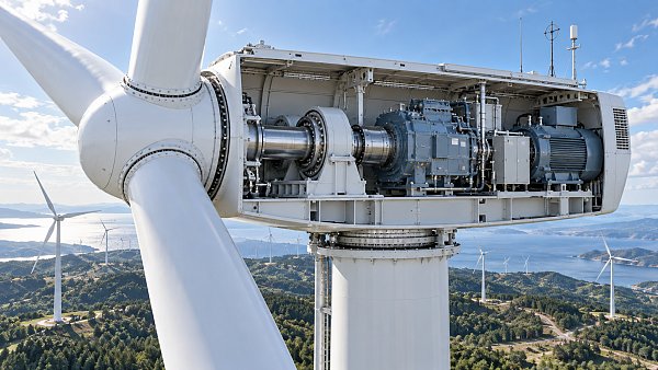
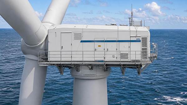
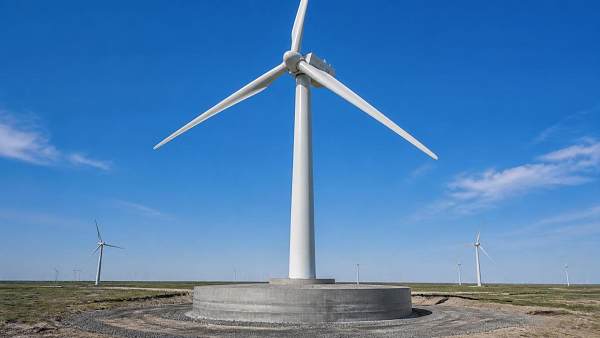
The nacelle of a wind turbine is the enclosed structure mounted behind the rotor at the top of the tower. It is more than a protective housing: it contains the drivetrain, electrical equipment, control hardware, cooling systems, and safety equipment that allow the turbine to turn wind into usable electricity.
For anyone assessing a wind project, the nacelle deserves attention because its design influences energy production, turbine availability, maintenance access, noise behavior, grid performance, and long-term operating cost. The blades may be the most visible part of a turbine, but many of the systems that determine whether the machine runs reliably are located inside the nacelle.
What the nacelle does
A wind turbine nacelle has three practical jobs. First, it supports and protects the mechanical equipment that receives rotation from the rotor. Second, it contains systems that convert that mechanical energy into electrical power and deliver it down the tower. Third, it actively controls the turbine so it faces the wind, operates within safe limits, and responds correctly to changing wind and grid conditions.
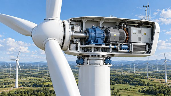
The nacelle is connected to the tower through the yaw system. This allows the entire nacelle, rotor, and blades to rotate horizontally so the rotor can face the incoming wind. In an upwind turbine, which is a common arrangement, the rotor sits in front of the nacelle. Downwind designs place the rotor behind it, but the internal operating requirements remain broadly similar.
Its outer shell is usually designed to resist weather, protect sensitive equipment from moisture and dust, manage airflow, and provide service access. The housing does not make a turbine weatherproof in a simple sense. Internal temperature, humidity, vibration, lubrication condition, and electrical faults still need active monitoring and control.
A practical view of the internal layout
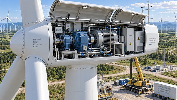
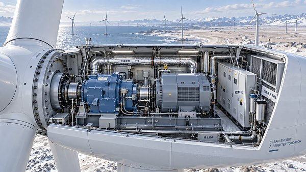
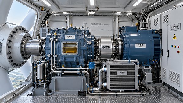
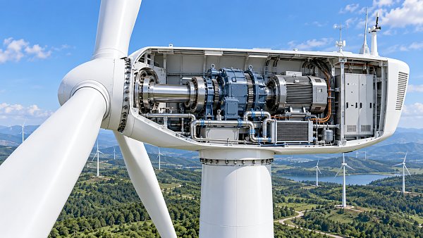
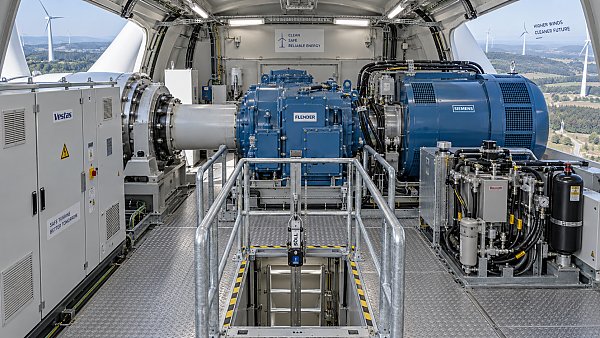
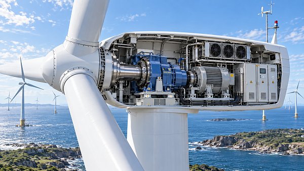
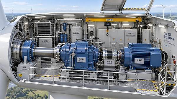
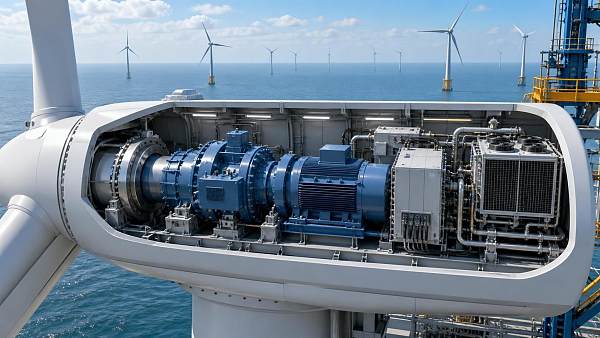
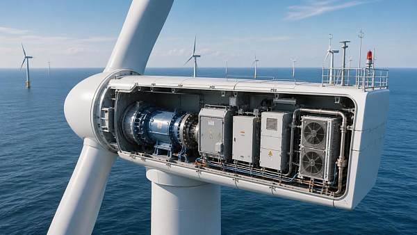
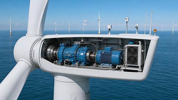
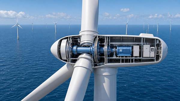
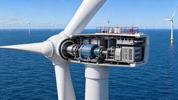
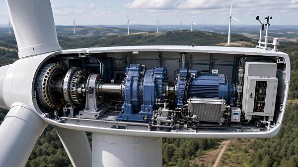
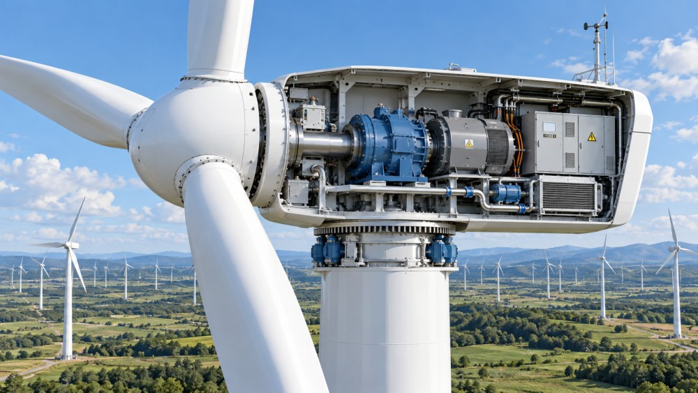
There is no single nacelle layout for every turbine. Equipment placement changes with turbine rating, drivetrain type, manufacturer design, offshore or onshore use, and maintenance philosophy. Still, the internal arrangement often follows the path of energy from the rotor toward the tower.
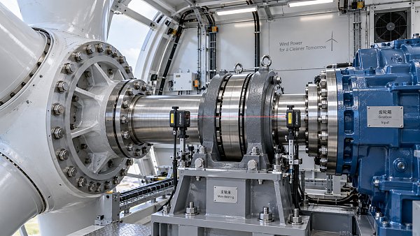
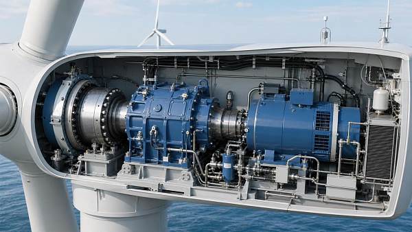
At the front is the main shaft, which receives rotational force from the hub and rotor. It is supported by bearings that must handle substantial and changing loads caused by wind direction, turbulence, blade movement, and rotor weight. A failure in this area can lead to extended downtime because access, lifting, and repair work at tower-top height are demanding.
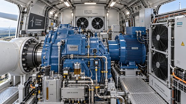
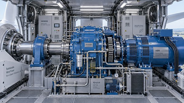
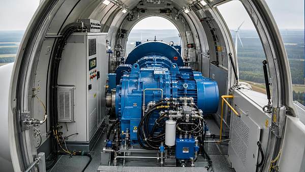
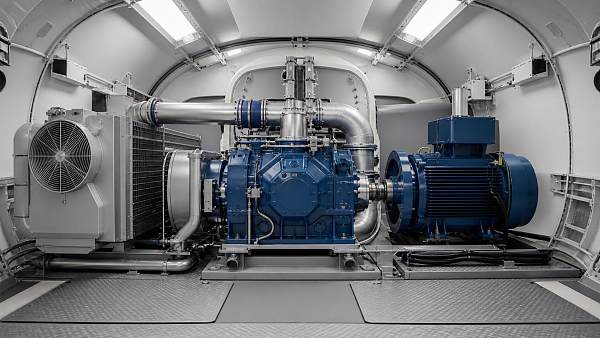
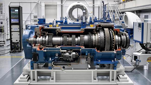
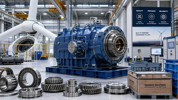
In many geared turbines, the shaft drives a gearbox. The rotor turns relatively slowly, while the generator normally requires a higher rotational speed. The gearbox increases that speed. Gearboxes are therefore a major part of the nacelle in this turbine configuration, along with lubrication, filtration, oil cooling, vibration sensing, and condition-monitoring equipment.
In a direct-drive turbine, the gearbox is removed. The generator is designed to operate at the rotor's lower speed, often with a larger generator assembly. Removing a gearbox can reduce one category of mechanical complexity, but it does not eliminate maintenance needs. Bearing loads, electrical systems, cooling, access constraints, and generator reliability still matter.
Behind or around the drivetrain sits the generator, which converts rotational mechanical energy into electrical energy. The output then passes through electrical cabinets and power electronics before electricity travels down the tower through cables. Depending on the turbine architecture, parts of the conversion and voltage-management equipment may be inside the nacelle, tower base, or both.
The systems that keep the turbine operating
A nacelle is best understood as a coordinated operating environment rather than a collection of separate parts. The following systems work together continuously.
Yaw and pitch are not the same thing
These two systems are often confused because both affect how the turbine interacts with wind. The yaw system turns the entire nacelle around the vertical axis of the tower, aligning the rotor with wind direction. The pitch system changes the angle of individual blades.
Pitch control is especially important because it regulates aerodynamic force. When wind conditions are suitable, blades are pitched to capture energy efficiently. When the wind becomes too strong or a fault occurs, the blades can move toward a feathered position that reduces lift and slows the rotor. This makes pitch control part of normal production control as well as turbine protection.
Braking is a layered safety function
People sometimes assume that a turbine stops through one large mechanical brake. In reality, controlled blade pitching is usually the primary method for reducing rotor speed. A mechanical brake in the drivetrain may be used as a holding or secondary braking device, particularly once rotor speed has been reduced.
This distinction matters when reviewing turbine systems. A safe shutdown depends on control logic, pitch actuation, reliable backup power for critical functions, brake capability, sensors, and the ability to communicate fault conditions. It should not be assessed as a single component feature.
Electrical systems inside the nacelle
The electrical side of the nacelle has become more important as wind plants are expected to support a more flexible power system. The generator produces electricity, but that electricity must be controlled before it is delivered to the collection network. Power converters, switchgear, transformers in some designs, protection devices, and control cabinets help manage that process.
Modern turbines need to do more than generate whenever the wind blows. They may need to limit output, respond to voltage changes, support reactive power control, remain stable through certain grid disturbances, and communicate with the wind plant controller. The exact capability depends on the turbine and project requirements, but the nacelle's electrical and control architecture is central to meeting them.
For project planners, this is why turbine selection should not focus only on rated output or rotor diameter. The ability to integrate with local grid requirements, plant controls, substations, energy storage, and curtailment strategies can affect the usable value of generation. EPEM's wider coverage of wind power, grid modernization, storage, and digital energy systems reflects this connection: a turbine is an asset within a power system, not an isolated machine.
Cooling, lubrication, and environmental control
Mechanical movement and electrical conversion generate heat. Inside a confined nacelle, heat management is necessary for drivetrain equipment, converters, transformers where installed, generators, and control cabinets. Cooling may involve air circulation, liquid cooling, heat exchangers, fans, filters, or a combination of methods.
Environmental control is not only about preventing overheating. Condensation, salt exposure in offshore environments, dust, insects, oil leaks, and airborne contaminants can degrade equipment over time. A cooling arrangement that works well in one climate may impose different maintenance demands in a hot, humid, dusty, or marine location.
Lubrication systems deserve similar attention. In a geared machine, lubricating oil supports gearbox operation and carries heat and contamination away from contact surfaces. Filters, pumps, sensors, and oil-condition monitoring are part of the reliability picture. Looking only at the gearbox specification without examining the supporting lubrication and monitoring approach gives an incomplete view of maintenance risk.
What is monitored in a wind turbine nacelle?
Control systems collect operating data from across the turbine. Common monitored conditions include wind speed and direction, rotor speed, nacelle position, generator temperature, bearing temperature, vibration, hydraulic or pitch-system status, electrical output, cabinet temperature, and fault states.
These signals are used by the turbine controller and typically shared with supervisory monitoring systems. The purpose is not merely to create a dashboard. Monitoring supports automated control decisions, alarms, preventive maintenance planning, remote troubleshooting, and fleet-level performance analysis.
Condition monitoring is particularly useful when it helps operators distinguish between a temporary variation and a developing problem. A single high temperature reading may have several causes. A persistent temperature trend combined with vibration changes, lubrication alarms, or declining performance is more meaningful. Data needs operating context before it becomes an actionable maintenance decision.
Why nacelle design affects maintenance cost
Maintenance work inside a nacelle is constrained by height, weather, confined space, lifting capacity, and the availability of trained technicians. A component can be technically serviceable yet costly to repair if access is poor or major lifting equipment is required.
For that reason, project evaluation should include questions beyond component names:
- Can technicians safely reach filters, sensors, pumps, electrical cabinets, and service points?
- Which tasks can be completed with internal lifting equipment, and which require external cranes?
- How are gearbox oil, cooling fluids, and other consumables inspected or replaced?
- How much redundancy exists for controls, cooling, pitch actuation, and critical communications?
- Can faults be diagnosed remotely before a service crew travels to the site?
- Are spare parts, specialist tools, and qualified service support realistic for the project location?
Offshore projects make these questions more consequential because access can be limited by sea conditions and vessel availability. In remote onshore sites, travel time, road access, weather windows, and crane logistics can create similar concerns. The most suitable nacelle arrangement is therefore not simply the one with the fewest visible components; it is one that matches the site's operating and service conditions.
Common misunderstandings when comparing turbines
A nacelle is not just the cover behind the blades. The shell is visible, but the nacelle is a functional system containing much of the turbine's mechanical, electrical, and operational infrastructure.
Gearbox-free does not mean maintenance-free. Direct-drive configurations remove the gearbox, but they still rely on large bearings, generators, cooling, converters, controls, and yaw and pitch systems. The maintenance profile changes rather than disappearing.
A larger nacelle is not automatically a disadvantage. Size may reflect generator configuration, cooling needs, service space, structural requirements, or component arrangement. What matters is how the design performs under the intended wind, climate, grid, and maintenance conditions.
Power rating alone does not describe operating value. Two turbines with similar output ratings may differ in rotor characteristics, control systems, grid capabilities, load behavior, service concept, and compatibility with the intended site. Nacelle-related systems are part of that difference.
What to examine next
When researching a turbine, start by identifying its drivetrain architecture: geared, medium-speed, or direct drive. Then look at the yaw and pitch arrangement, generator and converter design, cooling strategy, monitoring functions, access layout, and planned maintenance model. These areas provide a clearer picture of how the turbine is likely to operate than a simplified component list.
For developers, EPC teams, utilities, and investors, the nacelle should be reviewed alongside site wind conditions, transport constraints, grid connection requirements, crane strategy, service availability, and the intended operating life of the asset. The internal systems determine how effectively the turbine converts wind into power, but they also shape how predictable that power plant will be to operate and maintain.
Questions about market trends? Contact Market Scope Live for deeper business insights.
We respect your privacy. Your information is strictly confidential.
Related News
 Wind Power ComponentsDistributed Wind Energy Systems: How They Work and Where They FitDistributed wind energy systems can power farms, businesses, and communities. Discover how they work, where they fit, and what makes a project viable.MORE+
 Wind Power ComponentsTroubleshooting Nacelle Wind Turbine Parts That Cause Unplanned DowntimeTroubleshoot nacelle wind turbine parts with proven checks for gearbox, generator, yaw, hydraulic, and wiring faults to reduce unplanned downtime.MORE+
 Wind Power ComponentsHow to Evaluate Wind Turbine Blades for Fatigue Life, Erosion, and Site LoadsWind turbine blades: learn how to assess fatigue life, leading-edge erosion, lightning exposure, and site-specific loads to improve reliability, energy yield, and lifecycle decisions.MORE+
 Wind Power ComponentsNacelle of Wind Turbine: Lifecycle Cost Drivers Buyers Should EvaluateNacelle of wind turbine lifecycle costs: evaluate drivetrain design, service access, warranty scope, spares, and availability risks before buying.MORE+
 Wind Power ComponentsSelecting a Nacelle in Wind Turbine Projects for Cold, Coastal, and Dusty SitesNacelle in wind turbine selection guide for cold, coastal, and dusty sites—compare sealing, corrosion control, thermal management, filtration, and maintenance access.MORE+
 Wind Power ComponentsNacelle and Hub Interfaces: Alignment Risks That Can Shorten Turbine LifeNacelle and hub alignment risks can accelerate turbine wear. Learn how precise interface control protects drivetrain life, uptime, and project value.MORE+
 Wind Power ComponentsInside a Wind Turbine Nacelle: Which Components Need the Most Maintenance?Inside nacelle wind turbine systems, discover which components demand the most maintenance—from gearboxes to cooling and controls—and protect uptime with smarter inspections.MORE+
 Wind Power ComponentsNacelle Wind Turbine Parts: An Inspection Checklist for Preventing DowntimeNacelle wind turbine parts inspection checklist: detect early faults in drivetrain, cooling, yaw, brakes, and controls to prevent costly downtime.MORE+
 Wind Power ComponentsWhat Is a Nacelle in a Wind Turbine? The Systems That Control Power GenerationWhat is a nacelle in a wind turbine? Explore the drivetrain, controls, pitch, yaw, cooling, and safety systems that shape power output, reliability, and lifecycle costs.MORE+
 Wind Power ComponentsWhat Is a Nacelle on a Wind Turbine? Safe Access Rules for Field OperatorsWhat is a nacelle on a wind turbine? Explore its vital systems, key hazards, and safe access rules that help field operators protect people and turbine uptime.MORE+
 Wind Power ComponentsWhat Is Nacelle in Wind Turbine Design and Why Does It Affect Energy Output?What is nacelle in wind turbine design? Discover how this vital housing supports alignment, cooling, controls, and reliable energy output.MORE+
 Wind Power ComponentsThe Nacelle of a Wind Turbine Explained: Functions, Layout, and Key SystemsNacelle of a wind turbine explained: explore its drivetrain, yaw, pitch, cooling, electrical, and control systems—and see how nacelle design impacts reliability, maintenance, and energy output.MORE+
 Wind Power ComponentsWind Turbine Hub and Nacelle: How Loads Travel from Blades to DrivetrainWind turbine hub and nacelle: discover how blade loads flow through bearings, shafts, gearboxes, and supports to improve drivetrain reliability and maintenance decisions.MORE+
 Wind Power ComponentsInside a Wind Turbine Nacelle: How Drivetrain Layout Affects Maintenance AccessExplore how drivetrain layout inside the nacelle of wind turbine shapes maintenance access, lifting routes, safety, and lifecycle service costs.MORE+
 Wind Power ComponentsWhat is shaping the wind turbine nacelle market today?Wind turbine nacelle market trends: explore turbine scaling, drivetrain choices, reliability, grid compliance, localization, and offshore supply risks shaping smarter investment decisions.MORE+
 Wind Power ComponentsHow to inspect a wind turbine nacelle before commissioningWind turbine nacelle inspection guide: verify mechanical, electrical, safety, fire-protection, and documentation readiness before commissioning.MORE+
 Wind Power ComponentsWhich nacelle of wind turbine design suits offshore projects?Nacelle of wind turbine design for offshore projects: explore drivetrain options, marine protection, maintenance access, and vessel logistics for reliable performance.MORE+
 Wind Power ComponentsWhat should operators check when a wind turbine nacelle overheats?Nacelle wind turbine overheating? Learn the essential checks for cooling, gearbox, generator, and electrical systems to prevent failures and protect uptime.MORE+
 Wind Power ComponentsHow does nacelle cooling protect wind energy turbines?Wind energy nacelle cooling protects turbines from overheating, derating, and costly failures. Discover practical maintenance insights to improve reliability and power availability.MORE+
 Wind Power ComponentsWhat drives wind power nacelle maintenance costs over time?Wind power nacelle maintenance costs evolve with age, failures, access, parts, and downtime. Discover key risks and smarter lifecycle cost controls.MORE+
 Wind Power ComponentsHow does turbine nacelle weight affect foundation design?Turbine nacelle weight affects foundation loads, dynamics, fatigue, soil response, and crane planning. Discover key design factors for reliable wind projects.MORE+
 Wind Power ComponentsWhich nacelle components affect wind turbine reliability most?Nacelle components wind turbine reliability depends on drivetrain, generator, bearings, yaw, cooling, and controls. Explore high-impact risks and smarter maintenance priorities.MORE+
 Wind Power ComponentsHow are the nacelle and hub different in a wind turbine?Nacelle and hub: discover how these vital wind turbine components differ, from blade control and power conversion to maintenance, reliability, and project performance.MORE+
 Wind Power ComponentsWhat does a nacelle in a wind turbine actually do?Discover what a nacelle in wind turbine does, from power conversion and controls to maintenance, reliability, and wind farm economics. Read the full guide.MORE+
 Wind Power ComponentsHow Grid-Connected Wind Energy Systems Work in Utility and Commercial ProjectsGrid connected wind energy systems explained for utility and commercial projects—learn how turbines, substations, controls, and grid compliance shape reliable, bankable performance.MORE+
 Wind Power ComponentsWhat Does a Wind Turbine Nacelle Include and Why Does It Matter in Turbine Design?Wind turbine nacelles include the drivetrain, generator, controls, cooling, and service systems. Learn why nacelle design directly impacts reliability, maintenance cost, and turbine performance.MORE+
 Wind Power ComponentsHow to Evaluate Wind Turbine Gearboxes for Reliability, Load Capacity, and Service LifeWind turbine gearboxes evaluation starts with real duty profiles. Learn how to assess reliability, load capacity, lubrication, and service life for smarter supplier decisions.MORE+
 Wind Power ComponentsHow to Evaluate a Wind Turbine Gearboxes Manufacturer for Quality, Lead Time, and OEM FitWind turbine gearboxes manufacturer selection made simple: learn how to assess quality, lead time, OEM fit, warranty, and total cost to reduce project risk and improve uptime.MORE+
 Wind Power ComponentsHow to Choose a Wind Turbine Gearboxes Supplier for Reliability and Service SupportWind turbine gearboxes supplier selection affects uptime, lifecycle cost, and project risk. Learn how to compare reliability, service support, and delivery strength.MORE+
 Wind Power ComponentsWind Turbine Blades Explained: Materials, Blade Length, and Performance Trade-OffsWind turbine blades explained: compare materials, blade length, and performance trade-offs to improve energy yield, durability, and project ROI in modern wind power.MORE+
 Wind Power ComponentsIndustrial Gearboxes Selection Guide: Torque, Ratio, Duty Cycle, and Mounting BasicsGearboxes selection made practical: learn how torque, ratio, duty cycle, and mounting affect reliability, efficiency, and lifecycle cost in industrial applications.MORE+