
Turbine nacelle weight is often treated as a single number in early wind project planning. In foundation engineering, however, it is better understood as one part of a changing load system at the top of a tall, flexible structure. Its influence extends beyond the vertical force transferred to the ground. It affects tower-base forces, overturning moments, fatigue behavior, reinforcement detailing, crane planning, transport limits, and the sequence in which foundation and turbine packages can be released for construction.
For an onshore wind project, the practical question is not simply whether a heavier nacelle requires a larger foundation. In most cases, it does increase structural and geotechnical demand, but the magnitude of that increase depends on turbine geometry, rotor diameter, hub height, wind conditions, soil profile, groundwater, seismic requirements, and the manufacturer’s certified load cases. A foundation designed around incomplete turbine information can become either unnecessarily expensive or difficult to validate once the final turbine model is selected.
The nacelle is a major contributor to permanent gravity load
The nacelle contains the drivetrain or direct-drive generator, gearbox where applicable, transformer arrangement in some turbine configurations, yaw system, cooling equipment, converter equipment, controls, and auxiliary systems. Together with the rotor and hub, it forms the rotor-nacelle assembly, commonly referred to in structural documentation as the RNA.
Nacelle mass contributes directly to the permanent vertical load carried through the tower and into the foundation. The foundation must transfer this load safely into the supporting soil or rock while maintaining acceptable settlement and tilt. As turbine ratings increase, nacelles and rotor assemblies generally become heavier, although the relationship is not linear. Direct-drive machines may have a comparatively heavy generator, while geared designs distribute drivetrain mass differently. Equipment layout, transformer location, and tower design can also change the load presented at the tower base.
For preliminary civil planning, the dead load matters because it establishes the baseline contact pressure under the foundation. On a gravity foundation, additional permanent mass can improve resistance to uplift under some extreme wind cases. Yet this apparent benefit should not be overstated. A heavier turbine also creates larger inertial effects and may increase tower-base actions during operation, shutdown, fault events, and turbulence-driven loading. Foundation design is governed by combinations of actions, not by dead weight in isolation.
Why vertical mass is not the main design driver in every project
In many modern onshore turbines, overturning moment and cyclic loading govern more critical aspects of foundation sizing than the nacelle’s vertical weight alone. Wind acting on the rotor produces thrust. That thrust is applied high above ground level, creating a large overturning moment at the tower base. Rotor rotation, yaw movement, emergency stops, parked survival conditions, and control-system responses add further dynamic actions.
The nacelle’s role is important because its mass is elevated at hub height. When the turbine structure accelerates or vibrates, the inertia associated with the nacelle and rotor assembly contributes to horizontal forces and bending moments. Increasing the RNA mass may alter the natural frequencies of the tower-foundation system. This is a serious design issue because the combined system must avoid unfavorable interaction with rotor rotational frequencies and other excitation sources over the operating range.
A foundation that is adequate for bearing pressure may therefore still be unsuitable if its stiffness does not support the required dynamic behavior. Conversely, simply adding concrete to make a foundation heavier is not always an efficient remedy. More mass may change the system response, but it can also raise cost, increase excavation volume, complicate logistics, and create new issues in weak or compressible soils.
The load path begins with certified turbine data, not a generic weight estimate
A frequent early-stage mistake is to size foundations using a nacelle mass quoted in a brochure or a preliminary supplier presentation. That figure may exclude the hub, blades, service equipment, fluids, optional systems, or site-specific components. It also says little about the full set of forces and moments required for design.
The civil designer needs the turbine supplier’s foundation load documentation, normally issued for the specific turbine configuration, tower option, hub height, and site classification. Depending on the procurement structure, this may include a tower-base load envelope or a detailed load table covering relevant design load cases. The documentation should identify:
- permanent vertical actions from the tower and rotor-nacelle assembly;
- maximum and minimum vertical forces;
- horizontal shear forces in multiple directions;
- overturning moments about principal axes;
- torsional moments;
- fatigue load information or requirements for fatigue assessment;
- load factors, combination rules, and the applicable design standard;
- assumptions for wind class, turbulence category, operational mode, and seismic conditions.
These inputs are not interchangeable across turbine variants. A change from one hub height to another, an alternative tower supplier, a cold-climate package, a different grid-code configuration, or a turbine model revision can affect foundation reactions. Where the turbine supply contract is not finalized, civil works should not proceed on the assumption that any turbine of the same rated capacity will fit the same foundation.
Foundation type determines how nacelle weight is translated into design consequences
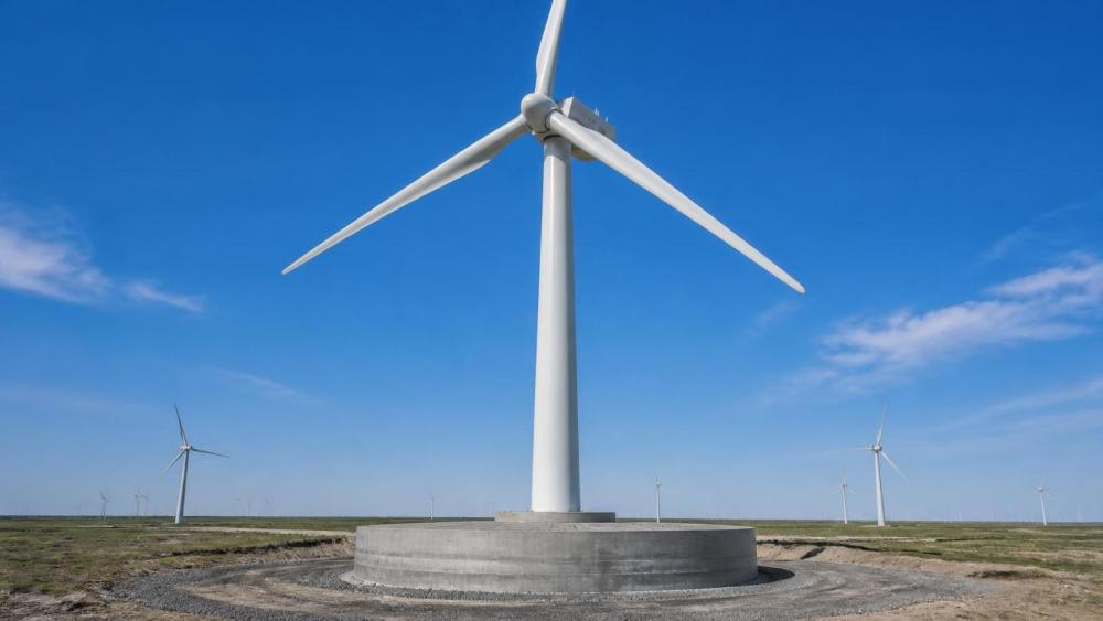
Most onshore projects use reinforced-concrete spread foundations, but the appropriate solution depends on ground conditions and turbine loads. A conventional circular gravity foundation transfers load through its base area and self-weight. In this arrangement, a heavier nacelle may increase average bearing pressure while also changing uplift behavior at the foundation edge under maximum overturning.
On competent rock or dense, low-compressibility soils, a spread footing may remain economical even for a large RNA, provided excavation and concrete supply are manageable. On soft clay, loose sand, variable fill, peat, or sites with a high groundwater table, the additional loads can trigger a different foundation concept. Options may include piled foundations, rock anchors, soil improvement, deeper founded systems, or a hybrid arrangement selected to control settlement and cyclic deformation.
Piled foundations are not merely a solution for vertical bearing capacity. They may be used where uplift, lateral response, differential settlement, or rotational stiffness cannot be controlled economically with a shallow footing. The nacelle and rotor assembly influence these demands because they affect both sustained loading and the dynamic load spectrum. However, pile design must consider group effects, cyclic axial loading, lateral behavior, pile-head connection details, and long-term soil response. Treating piles as a simple substitute for more concrete can produce an incomplete design.
Rock-anchor foundations can reduce concrete volumes in suitable bedrock conditions, but their viability depends on rock quality, discontinuities, groundwater, anchor testing, corrosion protection, and constructability. A high nacelle mass may increase anchor forces, yet the governing requirement can still be extreme overturning from rotor thrust rather than gravity load.
Geotechnical investigation must be matched to turbine scale
The larger the turbine and RNA, the less defensible it becomes to rely on generalized site geology or nearby building data. Wind turbine foundations impose high cyclic moments and require tight control of settlement and rotation. Even small long-term tilts can affect turbine operation, drainage behavior around the foundation, and warranty discussions.
A useful geotechnical campaign should establish not only allowable bearing resistance, but also soil stiffness parameters relevant to serviceability and dynamic analysis. The design team needs a coherent ground model: layer boundaries, variability across each turbine location, groundwater conditions, strength characteristics, compressibility, potential for frost action, liquefaction susceptibility where relevant, and rock-head profile. In heterogeneous terrain, a site-wide average is often less useful than location-specific risk classification.
Nacelle weight makes this especially important in projects where turbine selection is still evolving. A site initially evaluated for a smaller platform may have adequate ultimate bearing capacity for a newer turbine, but insufficient stiffness to meet rotation limits or fatigue assumptions. The difference can become visible only after the manufacturer’s final load set is applied.
Geotechnical uncertainty is also a commercial issue. If ground risks are not identified before foundation packages are tendered, the project may face change orders for over-excavation, dewatering, rock treatment, pile redesign, or local foundation enlargement. These changes affect not only civil cost but also turbine erection dates and crane scheduling.
Structural design is shaped by moments, fatigue, and connection details
A wind turbine foundation must resist repeated loading over a design life commonly measured in decades. The reinforcement design is therefore not based only on a one-time extreme event. Fatigue can be decisive around the tower interface, anchor cage, embedded steel components, and heavily stressed concrete zones.
The anchor cage or foundation connection is a particularly sensitive interface. It transfers tower-base tension and compression into the concrete foundation. Higher RNA mass can modify the axial force range experienced by the connection, while wind-generated overturning produces alternating tension in different anchor sectors. The design must account for the manufacturer’s connection requirements, bolt preload procedures, grout or flange details where applicable, tolerance limits, and the sequence of concrete placement and curing.
Reinforcement congestion is a practical warning sign. As turbine loads rise, designers may respond by increasing bar diameters, reducing spacing, thickening critical sections, or adding more radial and circumferential reinforcement. If detailing becomes too dense, concrete placement and vibration quality can suffer, especially around the anchor cage. A technically adequate calculation is not enough; the design must be buildable with the available concrete mix, placing equipment, workforce skill, and inspection regime.
Dynamic compatibility should be reviewed before the design is frozen
The tower, RNA, foundation, and soil form an integrated dynamic system. Their natural frequency must remain within the range required by the turbine manufacturer and applicable design methodology. The purpose is to avoid resonance or excessive amplification from rotor-related excitation, wind turbulence, and operational events.
This is why foundation stiffness is often as important as foundation strength. A softer soil profile can reduce the system frequency or increase damping uncertainty. A heavier turbine nacelle can have a similar effect by increasing the mass at the top of the tower. If the combined response falls into an unfavorable frequency zone, changing only the concrete volume may not solve the problem. The team may need to revise foundation geometry, improve the soil, change pile layout, adjust tower selection, or reconsider the turbine configuration.
Dynamic review should not be deferred until after procurement. By that point, foundation drawings, permits, supplier commitments, and construction schedules may already constrain options. Early collaboration among the turbine supplier, civil designer, geotechnical engineer, and owner’s engineer is the most effective way to prevent a late-stage mismatch.
Construction planning changes when the RNA becomes heavier
Nacelle weight affects the project beyond the finished foundation. Heavier components require larger erection cranes, higher ground-bearing capacity for crane pads, more demanding access-road geometry, and careful planning of delivery routes. Although these are not foundation design loads in the normal operating sense, they can change the civil scope substantially.
Crane pad design should be assessed separately from turbine foundation design. The ground may support the completed turbine foundation but still be unable to carry crawler-crane tracks or outrigger reactions without temporary improvement. On constrained sites, the choice of turbine and nacelle weight can determine whether crane assembly areas require extensive earthworks, geogrid reinforcement, imported aggregate, or seasonal construction restrictions.
Foundation curing time also matters. Large reinforced-concrete foundations may require thermal control measures, temperature monitoring, and a defined strength-development period before tower erection. A heavy nacelle does not automatically extend curing time, but the larger foundation dimensions and reinforcement density associated with higher loads can increase execution complexity. The schedule should include adequate time for excavation, subgrade acceptance, dewatering if needed, anchor cage installation, concrete placement, curing, backfilling, and survey verification.
How to manage turbine selection changes without losing control of civil risk
Wind projects commonly develop in stages. Energy yield studies may favor a larger rotor. Supply availability may change the shortlisted turbine models. Grid constraints can alter the preferred rated capacity. Each decision can affect the RNA mass and tower-base load envelope.
The most reliable approach is to establish a controlled design basis early. This should identify the turbine models being evaluated, the maximum credible hub height, preliminary RNA masses, required foundation load data, and the assumptions used in geotechnical and civil calculations. If the project proceeds with a provisional turbine, the team should define clear load limits that any final turbine must satisfy before it can use the same foundation design.
It is also useful to maintain a change register linking turbine changes to civil consequences. Changes worth formal review include nacelle mass, rotor diameter, hub height, tower type, tower-base diameter, anchor cage design, load factors, operating class, seismic configuration, and transformer location. The review should assess not only structural capacity but also dynamic compliance, crane requirements, access roads, drainage, and construction tolerances.
Overdesign is sometimes presented as a simple safeguard against these changes. It can be appropriate where multiple turbine options remain genuinely possible, but indiscriminate overdesign can consume large quantities of concrete and reinforcement without resolving dynamic or connection-interface issues. A disciplined reserve capacity strategy is preferable: design for defined ranges of vertical load, moment, shear, and stiffness requirements, then verify the final turbine against those limits.
The decision is about the complete turbine-foundation system
A heavier turbine nacelle generally increases the demands placed on a wind turbine foundation, but the engineering response should not be reduced to “make the footing bigger.” Its weight interacts with rotor thrust, tower flexibility, soil stiffness, cyclic loading, and construction logistics. The governing case may be bearing pressure, uplift, fatigue, settlement, dynamic frequency, anchor-cage demand, or crane-pad capacity depending on the site.
For onshore wind projects, the strongest risk control is to treat turbine selection, geotechnical characterization, foundation engineering, and erection planning as connected decisions. Secure certified load data early, test the ground model against the actual turbine scale, validate dynamic behavior, and keep turbine changes under formal engineering control. That process protects the foundation from being viewed as a civil package with a fixed price and turns it into what it really is: a critical interface between a high-value generating asset and the ground that must support it throughout its operating life.