
For most fixed-bottom offshore wind projects, the most suitable nacelle of wind turbine design is a modular, sealed medium-speed or direct-drive arrangement with marine-grade corrosion protection, redundant cooling and lubrication functions, and maintenance access designed around limited weather windows. There is no universal best drivetrain. The preferred choice changes with turbine rating, distance from shore, wave climate, installation vessel limits, grid-code duties, and the project’s tolerance for major-component exchange offshore.
A nacelle that performs well on land can become expensive offshore if it depends on frequent inspections, has exposed auxiliary equipment, or requires a large crane vessel for routine corrective work. Selection should therefore begin with the failure consequences of each subsystem rather than with generator type alone. The practical question is whether a fault can be detected early, isolated safely, and corrected during an available service window without turning into a major campaign.
Start with drivetrain architecture
The drivetrain determines nacelle mass, internal layout, maintenance burden, thermal behavior, and the lifting strategy for major components. Three broad configurations are commonly considered: high-speed geared, medium-speed geared, and direct drive.
A high-speed geared nacelle uses a gearbox to increase rotor speed before the generator. It can use a relatively compact generator, which may reduce generator size and ease certain factory handling steps. However, the gearbox, high-speed shaft, bearings, couplings, and associated lubrication system introduce additional interfaces that require careful alignment, filtration, oil condition monitoring, and vibration surveillance. Offshore use does not rule out this design, but it increases the importance of gearbox validation, oil cleanliness control during assembly, and a realistic replacement plan.
Medium-speed geared designs reduce the gearbox ratio and typically use a larger generator than a conventional high-speed configuration. This can be a useful compromise where the project seeks to reduce high-speed drivetrain loads while avoiding the full generator diameter and magnetic material requirements associated with some direct-drive machines. The nacelle may be heavier than a high-speed geared alternative, yet the architecture can offer a manageable balance between component access and drivetrain simplification.
Direct-drive nacelles eliminate the main gearbox and couple a large, low-speed generator directly to the rotor shaft. Fewer rotating drivetrain stages can remove a major maintenance concern, particularly where gearbox exchange would require exceptional lifting capacity. The trade-off is a larger generator, heavier main drivetrain structure, and potentially more demanding transport, nacelle lifting, and generator repair arrangements. Direct drive should not be selected solely because it has fewer parts. Generator bearing access, converter reliability, sealing, cooling circuits, and contingency arrangements remain material offshore issues.
The chosen arrangement should be assessed against the complete turbine load path. Rotor thrust, bending moments, yaw misalignment, tower-top motion, and transient grid events are transmitted through the hub, main shaft, bearing system, bedplate, yaw system, and tower interface. A promising drivetrain on a component comparison sheet may still create difficult tower-head loads or installation limits when assessed as a complete turbine.
Generator choice affects the rest of the nacelle
Generator technology is closely tied to the selected drivetrain. Doubly fed induction generators, permanent-magnet synchronous generators, and electrically excited synchronous generators each create different dependencies in the nacelle design. The relevant offshore comparison includes converter arrangement, heat rejection, insulation durability, availability of critical materials, access to generator internals, and response to electrical disturbances.
Permanent-magnet machines are often associated with compact active generator components for a given torque requirement, especially in direct-drive or medium-speed applications. Their use may reduce certain excitation-related systems, but the project should examine magnet protection, corrosion control within the generator environment, supply-chain documentation, demagnetization margins under fault and temperature conditions, and procedures for internal repairs. A sealed enclosure is valuable only if pressure equalization, condensation control, and cable penetrations remain reliable through the design life.
Electrically excited synchronous machines avoid permanent magnets but introduce excitation equipment and associated control needs. In some configurations, the absence of magnets may be relevant to material sourcing and repair philosophy. The design still requires a clear assessment of rotor insulation, slip-ring or brushless excitation arrangements where applicable, thermal performance, and protection coordination with the converter and transformer.
Generator selection should not be separated from grid connection design. Offshore turbines may face voltage variation, reactive-power requirements, harmonic limits, fault ride-through duties, and long export cable effects. The nacelle converter, filters, transformer arrangement, control software, and protection settings must be compatible with the plant-level electrical design. A nacelle capable of strong mechanical availability can still create commissioning delays if its control envelope does not match the grid study assumptions.
Marine sealing and corrosion protection need subsystem-level detail
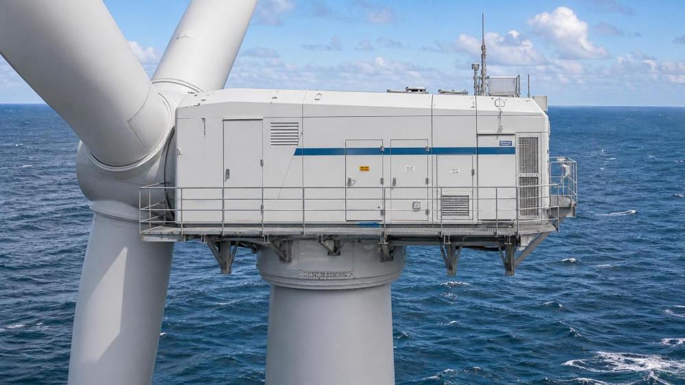
Salt-laden air enters through ventilation paths, maintenance openings, cable entries, imperfect gaskets, and pressure changes caused by temperature cycles. Treating corrosion protection as a paint specification alone is a common error. The nacelle of wind turbine should be reviewed as a collection of interfaces: bedplate welds, external fasteners, cooling connections, cabinet hinges, cable glands, service hatches, sensor housings, lifting points, and drainage routes.
Structural steel components generally need a coating system appropriate to the anticipated marine exposure, with surface preparation, edge treatment, dry-film thickness control, repair procedures, and inspection records defined before serial production. Galvanic pairs require particular attention. Stainless fasteners, aluminum housings, copper conductors, galvanized steel, and coated carbon steel can form corrosion cells if moisture bridges dissimilar materials. Isolation washers, compatible coatings, controlled fastener selection, and water-shedding geometry may be required.
Inside the nacelle, condensation can be as damaging as direct salt deposition. Electrical cabinets should have suitable enclosure protection, controlled breathing or dehumidification where needed, correctly routed drain paths, and cable glands sized for the actual cable diameter and movement. Cabinet heaters alone are not a complete moisture strategy; poorly placed heaters can create temperature gradients that encourage condensation elsewhere. Inspection access must allow seals and drains to be examined without dismantling unrelated equipment.
Cooling systems deserve the same scrutiny. Air cooling can simplify some equipment but may increase exposure to airborne contaminants. Closed liquid cooling can better protect sensitive converters and generators, provided hose materials, clamps, pump redundancy, leak detection, coolant chemistry, and heat-exchanger fouling controls are fully specified. If seawater is used indirectly through a separate circuit, material compatibility and isolation between circuits become especially important. A small coolant leak near converter cabinets can become a major availability event.
Design around offshore maintenance, not ideal access
Service tasks should be classified by the equipment, lifting method, weather limit, and time required to return the turbine to operation. This exposes whether the nacelle layout genuinely supports offshore work. Internal crane coverage, rail paths, removable roof sections, hatch dimensions, working clearances, anchor points, and rescue routes all influence the practical repair duration.
Components with known wear mechanisms should be positioned for inspection and replacement without removing large assemblies. Filters, pumps, fans, sensors, brake pads, yaw drives, lubrication cartridges, and control modules need visible identification, adequate hand clearance, and access under realistic lighting and personal protective equipment conditions. A densely packed nacelle may reduce external dimensions yet create long service durations when a minor component sits behind hydraulic pipework or high-voltage cabinets.
- Major drivetrain components need a documented extraction route, including the required crane capacity, lifting fixture, temporary supports, and the vessel configuration assumed for the work.
- Condition monitoring should cover the actual degradation mechanisms of the selected design: bearing vibration, gearbox debris, oil moisture, generator temperature, converter cooling performance, and yaw or pitch anomalies.
- Remote reset capability should be separated from fault diagnosis. Repeated remote resets can conceal an intermittent cooling, insulation, sensor, or control problem that later produces an extended outage.
- Emergency systems, including braking, fire detection, fire suppression where fitted, lighting, and communication, require inspection access and clearly defined functional tests.
Availability claims should be interpreted carefully. The relevant question is not only whether a component is reliable in normal operation, but whether its failure mode can be managed offshore. A replaceable converter module may be preferable to an integrated assembly if the latter requires prolonged tower-top work. Conversely, an overly modular design can add connectors and interfaces exposed to vibration and moisture. The strongest arrangement is usually the one with robust interfaces and a credible repair pathway for the few failures that cannot be avoided.
Mass, dimensions, and vessel logistics can eliminate otherwise attractive designs
Nacelle mass affects transport from factory to marshalling port, quayside bearing loads, storage fixtures, lifting slings, crane capacity, vessel stability, and installation sequence. The quoted nacelle mass should be defined clearly: bare nacelle, nacelle with generator, nacelle with service crane, or nacelle including specified fluids and loose equipment. Differences in definition can distort comparisons.
Transport envelopes require attention to center of gravity, lifting trunnion position, allowable accelerations, shipping supports, and vibration limits for sensitive components. Large direct-drive generators may need specialized lifting arrangements, while geared designs may require protection against lubricant migration or shaft movement during transport. These requirements should appear in the logistics interface register early enough to influence port selection and vessel contracting.
Installation also creates temporary load conditions that differ from normal operation. The nacelle may be suspended, parked at a specific yaw position, exposed to wind while awaiting mating, or connected before all auxiliary systems are commissioned. Verify lifting analyses, allowable wind speeds, bolt-tightening sequences, electrical termination access, and preservation requirements between delivery and energization. A design that assumes rapid installation can be vulnerable when weather interrupts the sequence.
Specify evidence, interfaces, and acceptance criteria
A useful technical specification states the operational requirement and the evidence needed to demonstrate it. Generic wording such as “offshore suitable” leaves too much open to interpretation. The specification can require environmental design assumptions, subsystem ingress protection, coating and repair documentation, corrosion compatibility records, cooling schematics, condition-monitoring architecture, maintainability drawings, lifting studies, and fault-response logic.
Factory acceptance should examine more than electrical output. Confirm cabinet sealing details, cable routing, torque-marking practices, hose restraint, drain design, labeling, lubrication lines, sensor accessibility, and packing protection. Software configuration management is also important. The turbine controller, converter controller, pitch system, yaw system, and plant supervisory controls need compatible versions, documented parameter ownership, and a controlled process for later changes.
Interface ownership must be explicit where the nacelle connects to the tower, blades, array cable, offshore substation controls, communications network, and marine access system. Ambiguous boundaries often appear during commissioning: an unexpected vibration alarm, a communication dropout, a grounding issue, or a cooling alarm may cross several package scopes. Assigning signal lists, grounding philosophy, alarm priorities, test responsibilities, and handover criteria before delivery reduces this uncertainty.
For a typical offshore project, a medium-speed or direct-drive nacelle with mature marine protection and a practical service concept is often the strongest starting point. A high-speed geared design can remain suitable where gearbox monitoring, lubrication control, access provisions, and major-component logistics are convincingly addressed. The final selection should follow the project’s actual maintenance window, vessel plan, grid connection conditions, and component replacement strategy rather than a simplified assumption that one drivetrain is inherently superior.