
A solar-powered EV charging project may look straightforward on a site plan: PV arrays generate electricity, chargers serve vehicles, and any surplus flows to the grid. In practice, the grid connection is often the part that determines whether the project is affordable, buildable, and reliable. A charging hub can be physically installed long before it receives permission to operate at its intended capacity.
Understanding solar farm grid connection requirements for EV charging is therefore essential for developers, EPC contractors, fleet operators, commercial property owners, utilities, and investors. The requirements do not come from one rulebook alone. They typically combine utility interconnection standards, local electrical codes, planning conditions, metering rules, export agreements, protection requirements, and the technical limits of the local distribution network.
The central question is not simply, “Can solar power the chargers?” It is: “How will solar generation, vehicle demand, storage, and the public grid behave together under normal operation, peak charging periods, faults, and changing weather?” A credible answer requires more than adding the nameplate capacity of PV modules and chargers.
Start with the operating profile, not the equipment list
Grid operators assess the point of common coupling (PCC): the location where a solar-plus-charging site connects to the utility network. Before selecting transformers, inverters, or charging cabinets, the project team should define what the site is expected to do throughout the day and across seasons.
For example, a workplace charging site may have vehicles connected during daylight hours, allowing a meaningful share of solar output to be used on site. A highway fast-charging hub has a very different profile. Its largest loads may occur in the evening, during holidays, or whenever several high-power chargers are used at once. Solar can reduce annual grid imports, but it may not reduce the required grid capacity to the same extent.
Early design should model at least four operating conditions:
- Maximum EV charging demand when solar generation is low or unavailable.
- Maximum solar output when charging demand is limited.
- Simultaneous high charging demand and high solar production.
- Abnormal or transitional conditions, including inverter trips, battery outages, charger ramping, and grid faults.
This assessment helps establish the import capacity, possible export capacity, battery power requirement, transformer rating, cable sizing, and control strategy. It also reveals a common misconception: a 1 MW solar installation does not automatically make a 1 MW charging hub independent of the grid. Time mismatch matters as much as annual energy production.
Interconnection studies shape the project before construction begins
Most utilities require a formal interconnection application for a solar farm, large rooftop PV system, battery system, or high-capacity EV charging installation. The exact process varies by market and grid operator, but it commonly begins with a preliminary capacity review and develops into technical studies once the proposed connection size is known.
These studies may examine load flow, short-circuit levels, voltage rise and voltage drop, thermal loading of cables and transformers, protection coordination, flicker, harmonic distortion, and the effect of generation exports on nearby feeders. In areas with high distributed solar penetration, the network may already experience reverse power flow at midday. Adding another export-capable project can trigger reinforcement requirements even if the site’s own demand is substantial at other times.
The outcome may include one or more of the following:
- A required upgrade to the local transformer, feeder, switchgear, or substation.
- A lower approved export limit than the proposed PV capacity.
- An obligation to install dynamic export control or generation curtailment.
- Specific reactive power, power factor, or voltage-control settings.
- Additional protection devices, remote trip capability, or utility communications.
- A staged connection arrangement while network reinforcement is completed.
For developers, the commercial importance is clear. A project that appears attractive using standard equipment costs can change substantially if the utility requires a dedicated feeder, a larger transformer, or upstream substation works. Grid studies should be treated as an early feasibility item, not a late permitting exercise.
Import capacity and export capacity are separate decisions
Many project teams focus on solar export, but EV charging sites can be constrained more severely by import capacity. DC fast chargers draw substantial power during vehicle charging sessions, and a site with several chargers may create sharp demand peaks. The utility needs to know the maximum coincident demand, not merely the number of charge points installed.
A managed charging system can reduce the requested import capacity by sharing available power across chargers. Instead of allowing every charger to operate at maximum output simultaneously, the energy management system allocates capacity according to vehicle state of charge, departure time, fleet priorities, tariff windows, and site limits. This approach is especially useful for depot charging, logistics facilities, and commercial fleets where vehicles are parked for predictable periods.
Export capacity is the maximum power the project is allowed to feed back to the network. It may be lower than the solar plant’s AC rating. Where that happens, the developer can choose among several design responses: oversize PV and curtail surplus output, add battery storage, increase on-site charging demand, or negotiate network upgrades. The preferred option depends on the local tariff structure, interconnection cost, operating profile, and value assigned to charging availability.
Transformer, switchgear, and cable design must reflect bidirectional power flow
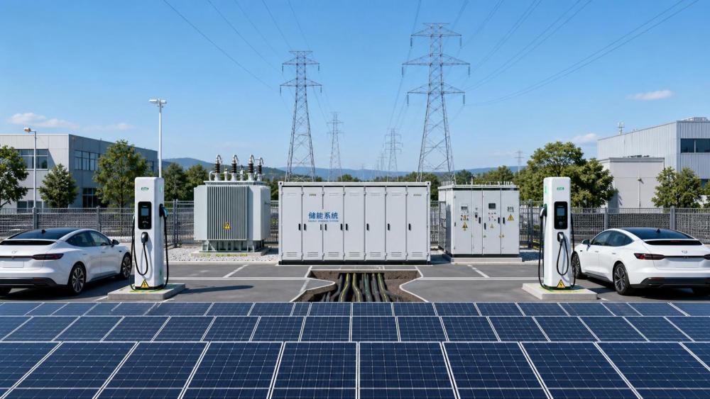
Traditional electrical designs often assume power flows one way—from the grid to the customer. Solar-powered EV charging changes that assumption. At different times, power may flow from the grid to chargers, from PV to chargers, from PV to the grid, from batteries to chargers, or from the grid into batteries. Equipment at the PCC must be specified for these operating modes.
Transformer sizing should consider maximum import and export conditions, anticipated harmonics, temperature rise, fault level, and future expansion. A transformer selected only for today’s charger load may become a bottleneck when PV, storage, or additional DC charging cabinets are added later. Similarly, switchgear ratings must suit the available short-circuit current and the protection philosophy required by the utility.
Cable routes deserve the same attention. Long runs between a solar field, battery enclosure, charging plaza, and grid connection point can create losses and voltage drop. Underground routing may also affect installation cost, thermal performance, and maintenance access. For large sites, electrical architecture—such as centralized versus distributed power conversion—can materially influence both connection works and lifecycle operations.
Inverters and charging equipment must meet grid-code expectations
Solar inverters are not simply conversion devices. They are active grid-connected assets that may be required to support voltage regulation, control reactive power, limit ramp rates, ride through certain disturbances, and disconnect safely when grid conditions exceed permitted limits. Requirements vary across jurisdictions, so project teams should confirm the applicable utility standard and national grid code before procurement.
Typical inverter-related requirements include anti-islanding protection, frequency and voltage trip settings, power factor capability, reactive power control, active power curtailment, remote communications, and low-voltage or high-voltage ride-through functions where applicable. Utilities may also require approved equipment lists or test certificates demonstrating compliance.
EV chargers introduce their own power-quality considerations. High-power DC chargers use power electronics and can contribute harmonics if system design is poor. The connection study may set limits for harmonic emissions, flicker, voltage unbalance, and rapid load changes. Harmonic filters, appropriately designed chargers, power quality monitoring, and coordinated control settings may be required, particularly at weak-grid locations.
Protection coordination is where integrated projects become technically demanding
Protection systems must isolate faults quickly while avoiding unnecessary shutdowns. This is more complicated when the site contains multiple generation and load sources. A fault on the utility network may require solar inverters and batteries to disconnect or respond in a prescribed way. A fault within the charging area should not necessarily trip the entire solar plant. Conversely, a fault in the solar collection system must not create unsafe backfeed conditions.
A coordinated protection design commonly considers circuit breakers, fuses, relays, residual-current protection, anti-islanding functions, earthing arrangements, surge protection, emergency shutdown devices, and utility-operated isolation points. Settings must be coordinated with the utility’s upstream protection so that the device closest to the fault clears it first where possible.
Commissioning is not merely a paperwork milestone. Utilities may require witnessed testing of protection relays, communications links, export controls, inverter settings, and disconnection functions before energization. Keeping an accurate settings register and single-line diagram is essential for later maintenance, expansion, and compliance audits.
Battery storage can improve flexibility, but it does not remove grid obligations
Battery energy storage is often proposed as the answer to grid constraints. It can be highly valuable: batteries can absorb midday solar surplus, reduce rapid charging peaks, avoid short-duration demand spikes, and support a capped export limit. For fleet depots, storage may also provide a buffer that keeps charging schedules on track when available grid capacity is limited.
Yet a battery changes the interconnection profile rather than making it disappear. The grid operator will want to know the battery’s maximum charge and discharge power, control logic, state-of-charge boundaries, fault response, and whether it can export independently of solar generation. If the battery is capable of discharging to the grid, it may be assessed as a separate generation source.
Fire safety, thermal management, isolation, and emergency response arrangements must also be incorporated into the project’s technical approval pathway. The most useful battery design begins with a clear operational purpose—solar shifting, peak shaving, resilience, export control, or charging support—rather than a generic storage capacity target.
Metering, communications, and control are often contractual requirements
Grid-connected charging projects need more than revenue meters. Depending on the connection agreement, the utility may require import/export metering at the PCC, generation metering, interval data collection, remote monitoring, telemetry, and a secure communications interface. These systems allow the operator to verify compliance with export caps and, in some cases, issue curtailment instructions.
An energy management system should sit at the center of the site’s operating logic. It can prioritize solar energy for charging, protect the grid import limit, maintain battery reserve, respond to electricity prices, and enforce an approved export setpoint. The control hierarchy must be carefully tested. If the solar inverter, battery controller, and charger management platform each pursue their own objective without coordination, unstable or inefficient behavior can result.
A practical approval checklist for developers and EPC teams
Before committing to final equipment orders, confirm that the project has addressed the following questions:
- What import and export capacities are requested, and are they supported by half-hourly or sub-hourly profiles?
- What is the approved point of connection, voltage level, and utility scope of works?
- Are solar, storage, and charger ratings aligned with the actual interconnection limits?
- Which grid-code functions, protection settings, certificates, and tests are mandatory?
- How will the site behave if solar output drops suddenly or several vehicles begin fast charging at once?
- Is the export-control scheme fail-safe, monitored, and accepted by the grid operator?
- Have future chargers, PV expansion, battery augmentation, and cable pathways been considered?
- Who owns responsibility for studies, utility coordination, commissioning evidence, and long-term compliance?
Grid connection is part of the business case, not a technical afterthought
Solar-powered EV charging can create a compelling energy model, especially where fleets, commercial sites, or public charging corridors need lower-carbon electricity and greater control over operating costs. But the value of the model depends on the connection being designed around real grid conditions. A larger solar array is not always the best answer; sometimes smart charging, a modest battery, export control, or a different connection point produces a stronger project outcome.
For organizations evaluating solar farms, charging hubs, storage systems, and distributed energy assets, EPEM tracks the technical and market factors that influence these decisions—from grid modernization and inverter compliance to charging architecture and project integration. The most resilient projects are those that treat the grid as an active partner in the design, rather than a final box to be checked after the equipment has been selected.
- grid modernization
- solar inverters
- DC fast chargers
- grid connection
- energy storage
- depot charging
- voltage regulation
- peak shaving
- power quality
- switchgear
- protection relays
- workplace charging
- interconnection standards
- EPC contractors
- grid operators
- commercial property owners
- fleet operators
- distributed energy
- solar farm
- charging hubs
- power electronics
- EV charging installation
- solar farm grid connection requirements for EV charging