Choosing String Inverters for Solar PV: Sizing, MPPT and Shading
Choosing string inverters for a solar PV project requires more than matching the inverter’s rated power to the array. DC-to-AC sizing, MPPT voltage and current limits, and the effects of partial shading can all influence energy yield and system performance. A sound comparison starts with the proposed string configuration and site conditions, then tests each inverter against the electrical, grid and operational requirements of the project.
The strongest candidate on a datasheet is not necessarily the best fit on the roof or in the field. An inverter with more MPPT trackers may simplify a fragmented commercial rooftop, while a simpler arrangement can work well on a uniform, unshaded array. The difference is often in how much usable energy the whole system can deliver over time, rather than in a single efficiency figure.
Start with the array, not the inverter nameplate
Before comparing models, establish the module type, proposed string lengths, orientations, expected shading and connection arrangement. These decisions determine the voltage and current presented to each inverter input. They also reveal whether nominally similar inverters offer enough flexibility for the physical layout.
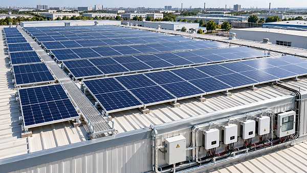
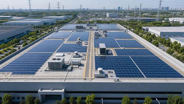
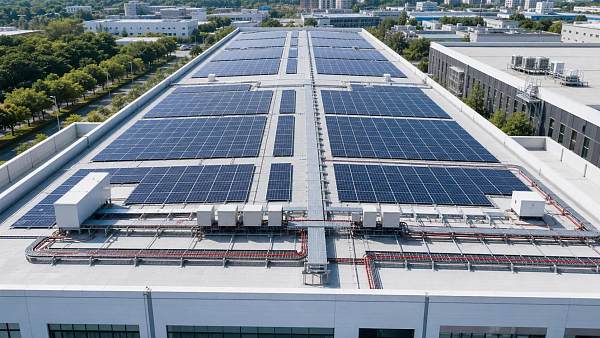
For example, a large industrial roof may contain several clean, similarly oriented blocks alongside smaller areas interrupted by equipment. Treating the whole roof as one electrically uniform array can hide mismatches between strings. Conversely, adding independent tracking to every small area may increase equipment and installation cost without recovering enough energy to justify it.
Prepare a preliminary string schedule before requesting final equipment quotations. Include module count per string, orientation, tilt, intended MPPT assignment and any known shading. The schedule makes it possible to test a design rather than compare product brochures in isolation.
DC-to-AC ratio: assess clipping against usable energy
The DC-to-AC ratio is the array’s rated DC power divided by the inverter’s rated AC output power, using a consistent basis. A ratio above one means the array’s nameplate capacity exceeds the inverter’s AC rating. This is common in PV design because modules do not operate at their nameplate rating throughout the day or year.
A larger DC array can improve inverter loading during lower-irradiance periods, but it can also increase clipping: energy that cannot be converted because the inverter has reached an output or operating limit. Clipping is not automatically a design failure. The relevant question is whether the additional energy produced at other times is worth more than the energy lost, given module cost, inverter cost, grid limits and the project’s revenue structure.
Compare candidate ratios using an hourly energy simulation rather than a single rule of thumb. Use the same weather data, module layout, degradation assumptions and electrical losses for each option. Check whether the model represents inverter temperature derating, export restrictions and site-specific shading; otherwise, the apparent advantage of one configuration may be misleading.
Also distinguish the inverter manufacturer’s permitted DC oversizing from the economically attractive ratio. A configuration can be electrically permitted but commercially unattractive. The reverse is also true: an appealing modeled yield does not make a design acceptable if it exceeds an equipment limit.
Check string voltage at both temperature extremes
The most consequential voltage check is usually the maximum open-circuit voltage on a cold day. Module voltage rises as cell temperature falls. Calculate the string’s temperature-corrected open-circuit voltage using the module manufacturer’s temperature coefficient and the design minimum temperature required by the applicable methodology. It must remain below the inverter’s maximum DC input voltage and any other applicable system limit.
At the other end of the range, hot modules operate at lower voltage. Check that the string’s operating voltage remains within the inverter’s MPPT operating range under relevant high-temperature conditions. A string that looks acceptable at standard test conditions may spend hot periods below the tracker’s usable range, limiting production or preventing normal operation.
Do not confuse the start-up voltage, absolute maximum DC voltage and MPPT voltage range. They answer different questions. Start-up voltage concerns when the inverter can begin operating; the MPPT range concerns where it can track; and maximum input voltage is a limit that must not be exceeded. Some models also specify a narrower voltage range for full rated power, so tracking within range does not necessarily mean full output is available.
The calculation should use the actual module datasheet and site design temperatures, not a generic module voltage. Leave appropriate design margin for the applicable standards, equipment instructions and uncertainty in the project inputs.
MPPT allocation is a layout decision
Maximum power point tracking adjusts the DC operating point to extract available power from a connected PV circuit. Independent MPPT trackers allow different groups of strings to operate at different voltages. That matters when array sections experience different irradiance, temperatures, orientations or shading patterns.
A useful starting point is to group strings with similar module types, string lengths, tilt, orientation and shade exposure on the same tracker, subject to the manufacturer’s instructions. East- and west-facing roof sections, for instance, may benefit from separate MPPTs because their production peaks occur at different times. The energy benefit still needs to be weighed against the cost and input capacity of the available inverter options.
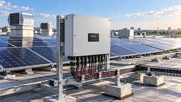
Pay attention to the difference between DC connectors and independent MPPTs. Multiple input pairs can be connected internally to the same tracker. More connectors may make wiring convenient, but they do not necessarily provide more independent operating points.
When parallel strings share an MPPT, their voltages are coupled. Different string lengths or substantially different conditions can create mismatch losses, and the resulting behavior depends on the modules and inverter. If an uneven layout forces a compromise, quantify it in the yield model and check whether the supplier permits the proposed connection.
Current limits can rule out an otherwise suitable inverter
Higher-current PV modules make it especially important to inspect the limits behind each input. Compare the module’s maximum power current and short-circuit current with the inverter’s stated limits, taking the number of parallel strings into account. Where bifacial modules are used, consider the manufacturer’s guidance on rear-side contribution and the resulting current under project conditions.
Datasheets may specify maximum operating current, maximum short-circuit current, limits per MPPT and limits per connector or input. These values are not interchangeable. Exceeding an operating current limit may lead to current limiting under some conditions; exceeding an absolute or permitted short-circuit limit may make the design unacceptable. The manufacturer’s definition and installation documentation determine how each limit applies.
Review string fusing, conductor sizing, connectors and DC protection alongside the inverter inputs. Parallel-string arrangements can change reverse-current protection requirements. The applicable electrical code, module maximum series-fuse rating and equipment instructions should govern the final design.
Treat shading as an electrical pattern, not just a percentage
A shade assessment should identify what is shaded, when and for how long. A vent that shades a few modules in the morning creates a different electrical problem from row-to-row shading across a large ground-mounted array. Shade can affect the current through a string and produce multiple peaks in its power-voltage curve, making tracking more complicated than under uniform sunlight.
Module bypass diodes can reduce some losses by allowing current around shaded cell groups, but they do not eliminate lost production. Their effect depends on the module’s internal layout and the shape of the shadow. Similarly, an inverter’s shade-management or global-scan function may help find a better operating point, but its behavior and scanning frequency should be checked rather than assumed equivalent across models.
Separate trackers can limit mismatch between shaded and unshaded groups. Module-level power electronics may be worth evaluating where shading is persistent or irregular, or where the layout cannot be grouped effectively. They add devices, connections and maintenance considerations, so compare their modeled energy benefit with installed cost and long-term service requirements. Where possible, avoiding the obstruction or changing the layout may be the simpler solution.
Grid behavior and site conditions affect the final choice
Electrical compatibility on the DC side is only part of selection. Confirm the AC voltage, frequency, phase arrangement and connection method against the project design. Grid operators may require particular settings or functions for voltage support, reactive power, ride-through, export control or communications. Applicable requirements vary by jurisdiction and connection agreement; a feature listed in a brochure should be checked against the actual grid approval process.
For a constrained connection, establish where export limits are measured and how the plant controller, meter and inverters respond. A nominal inverter rating alone does not explain how a site will behave when local loads change or communications fail. If storage or EV charging is planned, clarify whether the control architecture can coordinate those assets and which integration functions are supported by each supplier.
Environmental conditions deserve equal attention. Review ambient temperature, altitude, direct sunlight, dust, humidity, corrosion exposure and ventilation against the manufacturer’s installation requirements. Derating curves matter: an inverter installed in a hot, poorly ventilated location may deliver less AC power than its nameplate suggests during periods of strong solar production.
Compare lifecycle risk, not just conversion efficiency
Peak efficiency is useful, but it is not a complete energy-yield metric. Inverters operate across a range of voltages and loads, and system losses arise from wiring, mismatch, temperature, downtime and controls as well as conversion. Compare efficiency curves or weighted efficiency figures on a consistent basis, then include meaningful differences in the project model.
The number and size of inverters also affect maintenance. Distributed units can make replacement more localized, but they create more installation points and devices to monitor. Consider access routes, lifting requirements, spare-unit strategy, fault isolation and whether replacement hardware will require configuration or recommissioning. Warranty duration matters, but so do exclusions, response arrangements and the availability of local service and spare parts.
Monitoring granularity can change how quickly faults are found. Determine whether the proposed system reports inverter-level, MPPT-level or individual string data, and whether alarms and historical records can be accessed by the operator. Confirm communication interfaces, data ownership, cybersecurity requirements and any recurring platform charges before treating monitoring as a like-for-like feature.
A practical basis for the selection decision
A defensible shortlist should include a completed string schedule, cold-voltage and hot-operating-voltage checks, current calculations for every MPPT, and a documented shading assessment. Compare the remaining options with the same energy-model assumptions and record where the manufacturer has confirmed unusual string combinations, oversizing or control requirements.
For tender review, request the relevant datasheets, installation instructions, derating curves, grid-compliance documentation for the intended market, communications details and warranty terms. Confirm delivery timing and the process for resolving technical deviations before equipment is committed.
EPEM’s industry focus connects these equipment-level questions with wider project concerns, including grid integration, energy storage and long-term asset operation. For the immediate decision, however, the priority is concrete: select the inverter whose verified input limits, tracker allocation and operating behavior match the actual array—not simply the one with the closest AC rating.
Questions about market trends? Contact Market Scope Live for deeper business insights.
We respect your privacy. Your information is strictly confidential.
Related News
 Solar PV SystemsSolar Mounting Structures Pricing: What Drives Costs for PV Projects?Solar mounting structures pricing depends on design, materials and site conditions. Learn how to compare bids, uncover hidden costs and make smarter PV project decisions.MORE+
 Solar PV SystemsIndustrial Parks in Vietnam: Comparing Locations, Costs and InfrastructureCompare industrial parks in Vietnam by location, costs, logistics and power infrastructure. Discover how to shortlist the right site for your business.MORE+
 Solar PV SystemsFloating Solar Systems: How to Assess Reservoir SuitabilityFloating solar systems need the right reservoir. Discover how to assess water levels, grid access, environmental risks, and costs before investing.MORE+
 Solar PV SystemsSmart Solar Tracking Systems: How to Evaluate Energy Gains and Site SuitabilityExplore how smart solar tracking systems can boost energy yield. Compare site suitability, lifecycle costs, and fixed-tilt alternatives to make a confident investment decision.MORE+
 Solar PV SystemsFloating Solar Projects on Industrial Ponds: How to Assess Site SuitabilityAssess floating solar projects on industrial ponds with a practical guide to water levels, mooring, electrical connections, and site risks.MORE+
 Solar PV SystemsTurkey Allocates 785 MW of Grid Capacity in YEKA Solar TenderTurkey's YEKA solar tender allocates 785 MW of grid capacity across 11 sites. Explore what the results could mean for developers and suppliers.MORE+
 Solar PV SystemsChoosing String Inverters for Solar PV: Sizing, MPPT and ShadingChoose string inverters with confidence. Compare DC-to-AC sizing, MPPT allocation and shading impacts to improve solar PV performance.MORE+
 Solar PV SystemsChoosing Solar Racking Systems for Rooftops: Roof Type and Load FactorsChoosing solar racking systems for rooftops? Compare roof types, load factors and mounting options to plan a safer, more reliable installation.MORE+
 Solar PV SystemsSolar Tracking System Pricing: What to Include in a Project BudgetUnderstand solar tracking systems pricing and build a reliable project budget. Compare supplier quotes, uncover hidden costs, and assess long-term value.MORE+
 Solar PV SystemsChina Adds 110.83 GW of Solar in First Nine Months of 2026, Down 53.9%China solar additions reportedly fell 53.9% to 110.83 GW in January–September 2026. Explore pricing reform impacts and practical insights for project planning and procurement.MORE+
 Solar PV SystemsHow to Vet Solar Equipment Manufacturers: Quality, Warranties, and Lead TimesSearching “renewable equipment manufacturers solar”? Learn how to verify quality, compare warranties, and validate lead times to shortlist reliable suppliers and reduce project risk.MORE+
 Solar PV SystemsCommercial Rooftop Solar in India: How to Calculate Costs and PaybackCommercial rooftop solar India guide: calculate installation costs, estimate realistic savings and payback, and compare EPC quotes to make a smarter business investment.MORE+
 Solar PV SystemsSolar EPC Contractor Pricing: How to Compare Quotes and Spot ExclusionsCompare solar EPC contractor pricing with confidence. Learn how to spot exclusions, assess allowances, and uncover hidden costs before choosing the right quote for your project.MORE+
 Solar PV SystemsHow to Assess Site and Grid Feasibility for Solar Power Generation ProjectsAssess solar power generation projects with practical guidance on site suitability, grid capacity, connection costs, and curtailment risks. Make smarter investment decisions before committing capital.MORE+
 Solar PV SystemsPepco Approves ConnectDER Meter Adapters for Solar, Storage and EV Charging in D.C.Pepco approves ConnectDER meter adapters in D.C. for solar, storage and EV charging. Discover how meter-level connections could simplify installation and reduce costs.MORE+
 Solar PV SystemsTOPCon Photovoltaic Modules: Selection Criteria for High-Temperature Utility ProjectsTOPCon photovoltaic modules for hot-climate utility projects: compare temperature performance, bifacial yield, reliability, and electrical compatibility for stronger lifetime returns.MORE+
 Solar PV SystemsHow to Verify PV Module Supplier Capability Before Utility-Scale ProcurementVerify PV module supplier capability before utility-scale procurement with a practical checklist for factory audits, certifications, traceability, capacity, warranties, and risk control.MORE+
 Solar PV SystemsHow to Size Solar Power Generation Systems for Commercial Sites and Peak LoadsSolar power generation systems for commercial sites: learn to size PV for load profiles, peak demand, grid limits, storage, and future growth.MORE+
 Solar PV SystemsSolar Farm Construction: How to Plan Site, Grid Access, and Build RiskSolar farm construction insights for smarter site planning, grid access, procurement, and build-risk control—helping projects reach energization with confidence.MORE+
 Solar PV SystemsWhich Solar Inverter Certifications Are Mandatory in North America?What certifications are mandatory for solar inverters in North American markets? Explore UL 1741, IEEE 1547, CSA rules, and utility approval essentials.MORE+
 Solar PV SystemsWhat Is the Typical Payback Period for Commercial Solar PV in 2026?What is the typical payback period for a commercial solar PV installation in 2026? Explore the key cost, tariff, incentive, and sizing factors that shape returns.MORE+
 Solar PV SystemsWhat Causes Voltage Fluctuations When Large PV Plants Connect to Weak Grids?What causes voltage fluctuation when large solar PV plants connect to weak grids? Explore root causes, diagnostics, and proven mitigation strategies.MORE+
 Solar PV SystemsWhat Determines Solar Power Generation Efficiency in Commercial PV Projects?Solar power generation efficiency in commercial PV projects depends on more than module ratings—explore site resource, design, grid, and O&M factors that maximize long-term energy yield.MORE+
 Solar PV SystemsCommercial Rooftop Solar Financing: Comparing Loans, Leases, and PPAsCommercial rooftop solar financing explained: compare loans, leases, and PPAs to choose the right balance of savings, ownership, flexibility, and risk.MORE+
 Solar PV SystemsPV Bid Evaluation: How to Compare EPC Proposals Beyond the Lowest PricePV bid evaluation helps procurement teams compare EPC proposals beyond price—assess scope, energy yield, schedule, supply chain, warranties, and contract risk to protect long-term solar asset value.MORE+
 Solar PV SystemsWhat Environmental Permits Are Needed for Floating Solar on Reservoirs?What environmental permits are needed for floating solar on reservoirs? Explore water-use, EIA, shoreline, biodiversity, and water-quality approvals for smarter FPV development.MORE+
 Solar PV SystemsHow Long Does Utility-Scale Solar Grid Approval Take in 2026?How long does utility scale solar grid approval typically take in 2026? Explore timelines, queue risks, upgrade costs, and strategies to accelerate project delivery.MORE+
 Solar PV SystemsDo Agrivoltaic Projects Significantly Reduce Crop Yields in Hot Climates?Do agrivoltaic projects reduce crop yield significantly in hot climates? Explore how smart shade, crop selection, irrigation, and solar design can protect yields, improve quality, and strengthen dual-use land value.MORE+
 Solar PV SystemsHow Predictive Solar Plant O&M Reduces Downtime and Protects Energy YieldPredictive solar plant O&M helps cut downtime, detect faults early, prioritize repairs, and protect long-term energy yield with actionable data insights.MORE+
 Solar PV SystemsWhat Grid Connection Requirements Apply to Solar-Powered EV Charging?Solar farm grid connection requirements for EV charging explained: explore import/export limits, protection, storage, grid codes, and smart design strategies.MORE+
 Solar PV SystemsHow Much Solar Farm Capacity Is Needed to Offset Charging Demand in 2026?How to plan solar farm capacity to offset charging station demand in 2026? Explore sizing formulas, grid limits, storage strategies, and scalable EV charging solutions.MORE+
 Solar PV SystemsWhat Are the Actual Maintenance Costs of Solar Canopy Inverters?What are the real maintenance costs of solar inverters on charging canopies? Explore service, monitoring, repairs, downtime, and smarter lifecycle budgeting.MORE+
 Solar PV SystemsWhat Should Building Owners Evaluate Before Installing Rooftop Solar Photovoltaic?Rooftop solar photovoltaic planning starts with the right questions. Learn how to assess roof strength, load profile, grid limits, permits, and ROI before investing.MORE+
 Solar PV SystemsChina’s First Compute-Power and Green Power Direct Supply Project Enters OperationChina’s first compute-power and green power direct supply project begins operation, linking 500 MW solar power with data center demand for higher efficiency and stronger green energy credibility.MORE+
 Solar PV SystemsWhat Should Be Included in Solar Plant Engineering Design for Utility-Scale Projects?Solar plant engineering design for utility-scale projects should cover site constraints, layout, electrical systems, grid compliance, safety, and O&M—see what a complete, bankable design package must include.MORE+
 Solar PV SystemsUSTR Opens CVD Review on Chinese PV ModulesUSTR opens a CVD review on Chinese PV modules, raising questions over tariffs, sourcing, and Southeast Asia supply chains. See what importers and developers should watch now.MORE+
 Solar PV SystemsHow to Evaluate Rooftop Solar EPC Contractors for Commercial PV ProjectsRooftop solar EPC contractors can make or break commercial PV success. Learn how to compare engineering, grid, safety, scope, and risk control before choosing the right partner.MORE+
 Solar PV SystemsFixed Tilt Solar Racking: How to Evaluate Wind Load, Site Layout, and ROIFixed tilt solar racking guide: learn how to assess wind load, site layout, grading, foundations, and ROI to avoid hidden costs and choose a smarter solar structure.MORE+
 Solar PV SystemsHow to Choose Solar Modules for Commercial and Industrial PV Projects?Solar modules for C&I PV projects: learn how to compare efficiency, temperature performance, site suitability, warranty, and bankability to choose the right solution with confidence.MORE+
 Solar PV SystemsUSTR Extends Tariff Relief for Chinese PV ModulesUSTR Extends Tariff Relief for Chinese PV Modules through Dec. 31, 2026. See how the update affects solar procurement costs, project timelines, compliance, and U.S. market planning.MORE+